
Sometimes it is worth taking up well -known topics again, be it as an introduction to young programmers or deepening for the advanced. By updating the Raspberry Pi OS since my last attempts with the LCD, I also had to reinstall the program libraries (Python modules). And I came across a confusing variety of descriptions, circuit diagrams and sample programs on the Internet, which today can no longer work or even lead to damage. Since the program libraries on the product page and the descriptions in the eBook are no longer entirely up to date, I would like to take up the basics of installation and simple examples here in the blog.
Hardware used:
|
1 |
Raspberry Pi 3b, 4b or any Raspberry Pi With current Raspberry Pi OS (based on Debian Bullseye) |
Plus accessories |
|
1 |
||
|
1 |
||
|
1 |
||
|
1 |
Breakboard, preferably with breakout cable/adapter |
|
|
1 |
Sensor BME280 (Temperature, pressure, moisture) |
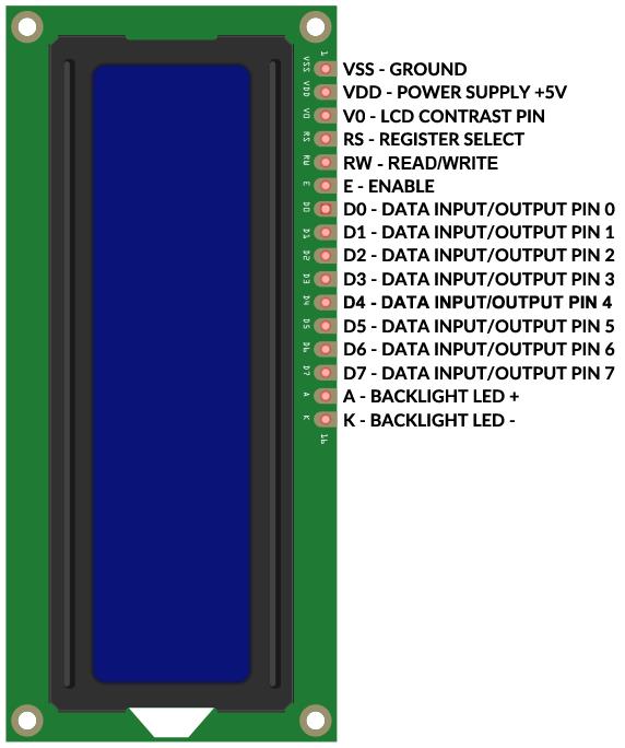
The pin assignment of the various LCDs 1602 and 2004, green or blue, is uniform as shown. 1602 means sixteen characters and two lines, in 2004 accordingly twenty characters in four lines. But be careful: the counting line/series (English) and the column (English column) begins in the 0. Example lcd.cursor_pos = (1.0) Put the cursor in the second line in the first position.
Libraries
The confusion of different libraries, especially for the different versions with and without i2C adapter, prompted the programmer Danilo Bargen to write a slim python module that takes into account all variants. If you read into the topic, you will find that you do not necessarily have to download, unzip and install the package from Github. Because it found its way into Pypi (The Python Package Index (Pypi) is a Repository of Software for the Python Programming Language.) And you can therefore install it directly on the Raspi with the Tool PIP.
The module means RPLCD, the terminal command is:
sudo PIP Install RPLCD
While the methods for operation, i.e. the actual Python program, are largely identical, you have to LCD Note whether the GPIO version or the I2C version of the display (see subsequent images) is used.
Here is the respective start of the programs ...
GPIO version:
 from RPI import GPIO
 GPIO.setwarning(False)
 from RPLCD.GPIO import Charlcd
 ## lcd = charlcd (pin_rs = 36, pin_rw = none, pin_e = 40, pins_data = [31, 33, 35, 37],
 ## Numbering_Mode = gpio.board, cols = 16, rows = 2, dotsize = 8,
 ## Charmap = 'A02', Auto_Linebreaks = True, Compat_Mode = True)

 LCD = Charlcd(Pin_rs=16, Pin_rw=None, pin_e=21, pins_data=[6, 13, 19, 26],
               Numbering_mode=GPIO.BCM,cols=16, rows=2, dots=8,
               charm='A02', auto_linebreaks=True, Compat_mode=True)
In addition two comments:
1. The (very long) line for GPIO.board, i.e. the physical PIN designations from 1 to 40. The unoborded line shows instantiation for GPIO.BCM, i.e. the PIN name with the GPIO numbers.
2. Of course, other pins can be used. I favor the last pins that cannot be used for the electronic interfaces (e.g. I2C, SPI). It is important that the circuit and pin numbers match instantiation.
I2C version:
 from RPLCD.I2C import Charlcd
 LCD = Charlcd('PCF8574',0x27)

 LCD.write_string('Hello World')
According to the simpler circuit with four lines for power supply and I2C interface, instantiation is also limited to the designation of the adapter used and the I2C address.
However, the hardware should not do without a Logic Level Converter (LLC). Of course I was curious and connected the I2C adapter directly to 3.3 V and 5 V. At 3.3 V, the display is very weak even when the potentiometer turns. At 5 V I measured the I2C pins 4.88V, so too much for the pins of the Raspberry Pi. The Book Says: 3.3V Max!
For me everything has stayed with healing and obviously also among the bloggers who publish the corresponding circuit diagrams on the Internet. But urgent recommendation: LLC as in the following picture:

Short note on the I2C adapter: In the illustration from the eBook, the i2C adapter is to be shown with its contacts. In fact, the adapter is soldered into "backpack", i.e. invisible below the LCD. It is crucial that the four connections are accessible to the page shown.
In the following tests I will use the GPIO version with the GPIO.BCM nomenclature. Here is the circuit diagram:

Sample programs
I would like to show the various options (methods/functions) of the module with the following Python programs. The program Helloworld.py or his equivalent Helloworldi2c.py First show the string 'Hello World' in the first line and then 'second line', then the display flashes, e.g. to attract attention, and finally the signs wander from the display. Finally, I would like to check whether all special characters are displayed.
 from RPI import GPIO
 GPIO.setwarning(False)
 from time import sleep
 from RPLCD.GPIO import Charlcd
 ## lcd = charlcd (pin_rs = 36, pin_rw = none, pin_e = 40, pins_data = [31, 33, 35, 37],
 ## Numbering_Mode = gpio.board, cols = 16, rows = 2, dotsize = 8,
 ## Charmap = 'A02', Auto_Linebreaks = True, Compat_Mode = True)

 LCD = Charlcd(Pin_rs=16, Pin_rw=None, pin_e=21, pins_data=[6, 13, 19, 26],
               Numbering_mode=GPIO.BCM,cols=16, rows=2, dots=8,
               charm='A02', auto_linebreaks=True, Compat_mode=True)

 LCD.clear()
 sleep(1)
 LCD.write_string('Hello World')
 LCD.cursor_pos = (1,0)
 LCD.write_string('Second line')
 sleep(3)

 for I in range(3):      # Display flashes every second
     sleep(1)
     LCD.Display_enabled=False
     sleep(1)
     LCD.Display_enabled=True

 sleep(1)
 for I in range(16):     # Text walks out to the left sign
     LCD.Shift_Display(-1)
     sleep(1)

 LCD.home()
 LCD.clear()

 # Try to write special characters
 LCD.write_string('!"§$%&/()=?²³<>|°{}[]+-*#,;.:')
 sleep(10)

 LCD.close(clear=True)
When displaying the special characters, the sign ° did not at all, the characters § and high numbers ² and ³ not displayed correctly. But since I would like to have ° C with the temperature display, I make use of the possibility of creating eight own characters from 8x5 pixels. An internet tool on page helps https://omerk.github.io/lcdchargen/.

It makes sense to copy the self -defined "character" in binary format and insert it in your own program as follows: (Download Helloworld_create_char.py)
 from RPI import GPIO
 GPIO.setwarning(False)
 from time import sleep
 from RPLCD.GPIO import Charlcd
 ## lcd = charlcd (pin_rs = 36, pin_rw = none, pin_e = 40, pins_data = [31, 33, 35, 37],
 ## Numbering_Mode = gpio.board, cols = 16, rows = 2, dotsize = 8,
 ## Charmap = 'A02', Auto_Linebreaks = True, Compat_Mode = True)

 LCD = Charlcd(Pin_rs=16, Pin_rw=None, pin_e=21, pins_data=[6, 13, 19, 26],
               Numbering_mode=GPIO.BCM,cols=16, rows=2, dots=8,
               charm='A02', auto_linebreaks=True, Compat_mode=True)

 LCD.clear()
 sleep(1)
 LCD.write_string('Hello World')
 LCD.cursor_pos = (1,0)
 LCD.write_string('Second line')
 sleep(3)

 LCD.home()
 LCD.clear()

 # Try to write special characters
 LCD.write_string('!"§$%&/()=?²³<>|°{}[]+-*#,;.:')
 sleep(5)

 degrees = (
     0b00111,
     0B00101,
     0b00111,
     0b00000,
     0b00000,
     0b00000,
     0b00000,
     0b00000)
 LCD.Create_char(0,degrees)

 smiley = (
     0b00000,
     0B01010,
     0B01010,
     0b00000,
     0B10001,
     0B10001,
     0B01110,
     0b00000)
 LCD.Create_char(1,smiley)

 para = (
     0B01111,
     0B10000,
     0B01110,
     0B10001,
     0B01110,
     0b00001,
     0B11110,
     0b00000)
 LCD.Create_char(3,para)

 LCD.clear()
 sleep(1)
 LCD.write_string('\ x00! "\ x03 $%&/() =? <> | {} []+-*#,;.: \ x01')

 sleep(10)

 LCD.close(clear=True)
Under the self -chosen variable names Degrees, Smiley and Para, the bitmaps are saved as the tupes of binary numbers. With the method
LCD-Create_Char (ARG1, ARG2) the characters are created. Is there arg1 The storage space, i.e. a number between 0 and 7, and arg2 The variable name of the tupel.
The character is displayed with the string \ x0z With Z= Storage space (0 ... 7). This can be done in the middle of the text. See example: The special characters of the German keyboard are displayed, starting with \ x00 = °, \ x03 = § between "and $ and the smiley at the end.
In the first example we had lcd.shift_display (-1) Seen with which the characters emigrated to the left (with +1 to the right). There is no method/ function in which a longer text is displayed as on the running tape. However, the module author has this in his blog Scrolling text with RPLCD presented as examples. I have developed this further so that the rolling text does not use the entire program. Download scrollingext.py
 from RPI import GPIO
 GPIO.setwarning(False)
 from time import sleep
 import _thread

 from RPLCD.GPIO import Charlcd
 ## lcd = charlcd (pin_rs = 36, pin_rw = none, pin_e = 40, pins_data = [31, 33, 35, 37],
 ## Numbering_Mode = gpio.board, cols = 16, rows = 2, dotsize = 8,
 ## Charmap = 'A02', Auto_Linebreaks = True, Compat_Mode = True)

 LCD = Charlcd(Pin_rs=16, Pin_rw=None, pin_e=21, pins_data=[6, 13, 19, 26],
               Numbering_mode=GPIO.BCM,cols=16, rows=2, dots=8,
               charm='A02', auto_linebreaks=True, Compat_mode=True)

 LCD.clear()
 sleep(1)

 frame buffer = [
     'Hello World!',
     '',
 ]
 line1 = 'Scrolling text'

 def write_to_lcd(LCD, frame buffer, num_cols):
     "" "" Write the Framebuffer Out to the Specified Lcd. "" "
     LCD.home()
     for row in frame buffer:
         LCD.write_string(row.lust(num_cols)[:num_cols])
         LCD.write_string('\ r \ n')

 def scroll_left(string, LCD, frame buffer, row, num_cols, delay=0.3):
     S = string
     IF (len(S) < num_cols):
         spaces = 3 + num_cols - len(S)
     Else:
         spaces = 3
     S = spaces*' ' + S
     while True:
         for I in range(num_cols):
             S = S[1:1+len(S)] + S[0]
             frame buffer[row] = S
             write_to_lcd(LCD, frame buffer, num_cols)
             sleep(delay)

 _thread.Start_new_thread(scroll_left,(line1, LCD, frame buffer, 1, 16))

 for n in range(10):
     print("N =",n)
     sleep(1)
Rolling the text is done in the self -defined function scroll_left (). Here the string is initially expanded by at least three spaces. Then in an endless loop with While True The character chain changes in such a way that the first character is cut off at the front and inserted again at the end. The technical terms for this are called "Slicing" and "Concation". So that the While True loop does not block the entire program, the function is executed in a so-called "thread". For this purpose, the corresponding module is with Import _thread imported. In the end, the self -defined function is called with
_thread.Start_new_thread(scroll_left,(line1, LCD, frame buffer, 1, 16))
The method Start_new_thread Has two arguments: First of all, the name of the function, which is called, without (), and a tupel with other parameters (the text to be output, the object LCD, the line number and number of characters per line).
Further information on the Python module RPLCD from Danilo Bargen under https://rplcd.readthedocs.io/en/stable/.
Temperature, air pressure and moisture sensor
Finally, I would like to expand the circuit with a combined temperature, air pressure and moisture sensor and display the values as well as the time on the LCD. For this, too, I take advantage of the preparatory work and install the corresponding program library (s).
Instead of a new circuit diagram, the simple pin assignment of the BME280:
- VCC to Phys. Pin 1 = 3.3V
- Gnd to Phys. Pin 9 (or another ground pin)
- SDA to Phys. Pin 3
- SCL to Phys. Pin 5
Of course, the I2C interface must be activated in the configuration and we check the I2C address in the terminal with the command
I2CDETECT - Y 1
In my case, the address is 0x76. That will be important later.
On the product page of the BME280 I find the module Adafruit_bme280.py And the sample program Adafruit_bme280_example.py. In the Readme.MD file, I read that further program libraries from Adafruit can be installed. So first in the terminal program:
 git clone https://github.com/adafruit/adafruit_python_gpio.git
 CD Adafruit_python_gpio
 sudo python setup.py install
The whole thing takes around half a minute.
Since the Adafruit module Adafruit_bme280.py When the I2C address uses 0x77 and you cannot change them as parameters as parameters in instantiation, I change the address to the 0x76 (see above) and save it. In the sample program I look at the functions and take over parts of it in my final project. Because of the long lines I recommend the download Lcd_bme280.py Instead of "copy and paste".
 From RPI Import GPIO
 Gpio.setwarning (false)
 Import time
 from adafruit_bme280 import *
 # I2c must be active, check address with i2cdetect - y 1
 # default is 0x77
 # if necessary, change address in modules adafruit_bme280.py

 sensor = BME280(T_Mode=Bme280_osample_8, P_Mode=Bme280_osample_8, h_mode=Bme280_osample_8)

 from rplcd.gpio import charlcd
 ## lcd = charlcd (pin_rs = 36, pin_rw = none, pin_e = 40, pins_data = [31, 33, 35, 37],
 ## Numbering_Mode = gpio.board, cols = 16, rows = 2, dotsize = 8,
 ## Charmap = 'A02', Auto_Linebreaks = True, Compat_Mode = True)

 LCD = Charlcd(Pin_rs=16, Pin_rw=None, pin_e=21, pins_data=[6, 13, 19, 26],
               Numbering_mode=Gpio.bcm, cols=16, rows=2, dots=8,
               charm='A02', auto_linebreaks=True, Compat_mode=True)

 lcd.clear ()
 Time.sleep (1)

 degrees = (
  0b00111,
  0B00101,
  0b00111,
  0b00000,
  0b00000,
  0b00000,
  0b00000,
  0b00000)
 lcd.create_char (0, degrees)

 while True:
  DTG = time.localime ()
     IF (dtg.tm_hour <10):
  hh = '0'+Str (dtg.tm_hour)
     Else:
  hh = Str (dtg.tm_hour)
     IF (dtg.tm_min <10):
  mm = '0'+str (dtg.tm_min)
     Else:
  mm = str (dtg.tm_min)
  Hhmm = hh + ':' + mm
  Print (HHMM)
  degrees = sensor.read_temperature ()
  pascals = sensor.read_Pressure ()
  hectopascals = Pascals / 100
  humidity = sensor.read_humidity ()

  print ('Temp = {0: 0.3f} ° C'. format (degrees))
  print ('Pressure = {0: 0.2f} hpa'. format (hectopascals))
  print ('Humidity = {0: 0.2f} %'. format (humidity))
     wx='T ='+Str (round (degrees, 1))+'\ x00c'+Hhmm+'\ r \ np ='+Str (round (hectopascals))+'hpa h ='+Str (round (humidity)))+'%'
  Print (WX)
  lcd.write_string (wx)
  Time.sleep (5)
  lcd.clear ()


Have fun recovery and adapting your own wishes.


