
After the Blog post Internet-radio with dem ESP32 a great echo hervoWe are now presenting a second variant, which has received numerous improvements and enhancements. The most significant change is the use of the I2S digital amplifier MAX98357A instead of the analog amplifier. The display was to 4 lines with 20 characters vergröures. Next to the station just played wou will find Date and time, and the current volume are displayed. The two lower lines show the Information about the current program that is sent along with the audio stream. The volumercontrol takes place justas well as the station selection via a rotary encoder. The configuration can be made, as with the improved version of Mr. Schröder (see update in the old post), via a Browser can be done. The channel list can also be changed and extended in this way.extended. Since some URLs are notplayable, a URL can now be tested via the browser configuration before it is saved.rt is saved. The supply via battery has been omitted, because the power consumption was too high. Additionally, a firmware update can be done via WLAN (Over The Air = OTA).
Required hardware
| Number | Component | Note |
|---|---|---|
|
1 |
|
|
|
2 |
|
|
|
1 |
|
|
|
1 |
|
|
|
1 |
|
|
|
1 |
|
|
|
1 |
|
|
|
2 |
|
|
|
1 |
|
|
|
2 |
|
|
|
2 |
|
|
|
1 |
|
|
|
1 |
|
|
|
2 |
|
|
|
2 |
Rotary knobs for 6mm axis |
|
|
Multiple |
|
|
|
1 |
|
|
|
1 |
|
Circuit

The following table shows the use of the Pins of the ESP32
|
Device |
Designation |
ESP32 |
| Amplifier left |
LRC |
25 |
|
BCLK |
26 |
|
|
DIN |
27 |
|
|
|
GAIN |
GND |
|
|
SD |
+5V |
|
|
GND |
GND |
|
VIN |
+5V |
|
| Amplifier right |
LRC |
25 |
|
BCLK |
26 |
|
|
|
DIN |
27 |
|
|
GAIN |
GND |
|
|
SD |
+5V via 470kΩ |
|
|
GND |
GND |
|
|
VIN |
+5V |
|
LCD display |
GND |
GND |
|
|
VCC |
+5V |
|
|
SDA |
21 |
|
|
SCL |
22 |
|
Encoder volume |
CLK |
14 |
|
|
DT |
13 |
|
|
SW |
|
|
|
+ |
+3.3V |
|
|
GND |
GND |
|
Encoder Transmitter selection |
CLK |
33 |
|
|
DT |
32 |
|
|
SW |
35 3.3V above10kΩ |
|
|
+ |
+3.3V |
|
|
GND |
GND |
|
Supply |
+5V |
VIN |
|
|
GND |
GND |
The ESP32 is assembled with the resistors and pin headers for the peripherals on a 50x70 mm breadboard. For the two 7-pin female connectors are used for the two amplifier modules.

The image shows the assembly and the wiring on the bottom side

The image shows the realization on a breadboard 50 x 70 mm
The wiring could also be done by a one-sided printedcircuit printed on one side. Only the red marked connection must be realized via a free connection. Three wire bridges are used for the I2S bus.
The two amplifier modules are plugged into the two 7-pin female connectors. The two rotary encoders and the display are connected with jumper wire cable F2F to the corresponding pin headers on the breadboard. The loudspeakers are connected to the screw terminals of the amplifier modules.

Software
The sketch was split into several parts for clarity. For this purpose a function is used, which is provided by the Arduino IDE. If there are other ".ino" or ".h" files in the same folder besides the main sketch, which has the same name as the folder, the compiler appends them to the main sketch in alphabetical order.
Since the whole code has become very large, it is only available for download.
Sketch for download
The ZIP file contains the folder with all related files. It has to be unpacked into the working directory of the Arduino IDE (mostly documents\Arduino\). In the following, the individual parts are briefly described. A detailed description can be found as comments in the code.
- ino: This is the main sketch. Global variables and data structures are defined.
- setup() after initializing the serial interface the configuration data is read from the preferences. Then the setup functions of the individual program parts are called, with the exception of web server and OTA. The connection to the local WLAN is established. If the connection was not successful, information about the configuration is shown on the display. If the connection is successful, the real-time clock is initialized and playback of the last station listened to is started. Now the setup for web server and OTA can also be called up.
- loop() first checks if there are OTA requests and then if there are requests for the web server. It checks if the connection to the WLAN still exists. If the connection exists, the audio stream and the two encoders are checked for events. Once per minute the display of the time is updated. If the connection was interrupted for more than 5 minutes, the ESP32 is restarted.
- ino: In this part all functions related to the audio streams are implemented.
- setup_audio() prepares the system. Buffer and stream output are initialized.
- audio_loop() checks the status of the audio stream.
- MDCallback(void *cbData, const char *type, bool isUnicode, const char *string)
is called whenever new metadata is available in the received stream. Metadata of type "Title" will be shown on the display. - stopPlaying() stops playing the stream and releases the associated resources.
- bool startUrl(String url) Starts playing a stream from a given URL. If the start is not successful, false is returned.
- setGain() sets the volume to the value of the global variable currentGain.
- ino: Contains functions to control the display and the definition of special characters like speaker and German umlauts.
- setup_display() initializes the display and creates the special characters in the display RAM.
- String extraChar(String text) replaces the German umlauts in the passed UTF8 text with the corresponding special character code.
- showStation() shows the name of the current radio station in the second line of the display. The display starts at position 2 and is truncated to 18 characters. If the current station is also the active station, the speaker symbol is displayed at position 0.
- displayMessage2(uint8_t line, String msg) the given string is displayed in two lines starting from the given line. Both lines will be deleted before. If the string has more than 20 characters, a line break occurs. The second line will be truncated after 20 characters.
- displayDateTime() The first line displays the date and time. In the rightmost position the current volume is displayed in percent.
- displayMessage(uint8_t line, String msg) the given string will be displayed in the given line. The line will be deleted before. The string will be truncated to a maximum of 20 characters.
- displayClear() deletes all four lines.
- clearLine(uint8_t line) deletes the specified line
- ino: Controls the volume control with a rotary encoder.
- gain_loop() checks if the value of the rotary encoder has changed. If it has, the new volume value is saved and set.
- IRAM_ATTR readGainISR() Interrupt handling for the encoder
- setup_gain() starts the encoder, registers the interrupt routine, sets the limits and the current value as default.
- h: Contains the HTML pages for the web server. With the command sequence
const char MAIN_page[] PROGMEM = R"=====(
any text.........
)=====";
an arbitrary text can be inserted directly as a constant into the program memory. This is very handy for HTML pages, as they can then be designed and tested outside the IDE. The present pages use jQuery, Ajax and JavaScript. The advantage of Ajax for interactive pages is that when changes are made, only the changed part of the page is updated. Three HTML constants are defined.- OPTION_entry a template for entries in the radio station selection list
- MAIN_page the main page with configuration and maintenance of the station list
- CONFIG_page Page for entering the access data if the ESP32 is in access point mode for initial configuration.
- ino: Here you can find the functions to update the firmware via WLAN.
- setup_ota() the host name and password are set. Then callback functions are registered.
- ota_onStart() is called at the start of an OTA upload. The display is cleared and a corresponding message is shown in the first line
- ota_onEnd() is called after the upload is finished. A corresponding message is displayed in the third line.
- ota_onProgress(unsigned int progress, unsigned int total) is called at regular intervals during the upload and provides information about the progress. The second line of the display shows the progress in percent.
- ota_onError(ota_error_t error) is called when an error occurs. The error message is then displayed in the fourth line.
- ino controls the station selection with a rotary encoder
- rotary_loop() checks if the value of the rotary encoder has changed. If it has, the next station from the station list is displayed. If the button on the encoder is pressed within 10 seconds, the new station is switched to. If the button is not pressed, there is no change and the current station is displayed again.
- IRAM_ATTR readRotaryISR() Interrupt handling for the encoder
- setup_rotary() starts the encoder, registers the interrupt routine, sets the limits and the current value as default.
- ino: defines a program memory constant with the default transmitter list.
- setup_senderlist() fills the station list in RAM with the station list from the preferences. If there is no station list there, the default station list is used.
- ino: Contains the setup and functions to respond to http requests.
- setup_webserver(): Registers the individual functions to handle http requests and starts the server on port 80.
- webserver_loop() it is checked if there are new requests.
- handleRoot() handles a request for the main page. If there is a connection to the local WLAN, the main page is sent to the client. If the ESP32 is in access point mode for the basic configuration, the configuration page is transmitted. In this case, any existing parameters must also be processed in order to save the access data or trigger a restart.
- sendStations() responds to the Ajax command with the URL /cmd/stations. Sends the list of stations as HTML optionlist. This list is then built into the dropdown element via javascript in the client.
- setAccessData() responds to the Ajax command with the URL /cmd/setaccess. The configuration data SSID, PKEY and NTP server are stored in the preferences.
- getAccessData() responds to the Ajax command with the URL /cmd/getaccess. The configuration data SSID, PKEY and NTP server are sent as response. The end of line is used as the separator.
- getStationData() responds to the Ajax command with the URL /cmd/getstation. The ID of the desired station is expected as argument. The name, URL and enable flag of the specified station is sent as response. The end of line is used as separator.
- setStationData() responds to the Ajax command with the URL /cmd/setstation. The ID of the desired station is expected as argument. If the ID is valid, the data passed as argument for the name, the URL and the enable flag will be stored in the station list.
- testStation() responds to the Ajax command with the URL /cmd/teststation. The URL to be tested is expected as an argument. An attempt is made to start the replay of the specified URL. If the attempt is not successful, it switches back to the current station and responds with "ERROR".
- endTest() responds to the Ajax command with the URL /cmd/endtest. The test is terminated by starting the playback of the current station.
- restart() responds to the Ajax command with the URL /cmd/restart. The ESP32 is restarted.
- ino: Contains the function to connect to the local WLAN or to provide an access point if a connection is not possible.
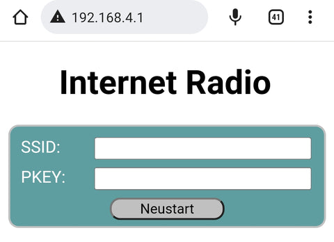
- boolean initWiFi(String ssid, String pkey) Attempts to connect to the local WLAN using the specified credentials. If no SSID is specified or the connection attempt fails, an access point is started. This access point can then be used to access the configuration page from a browser at the address 192.168.4.1.
In order to compile the sketch, the Arduino IDE must be prepared accordingly. The Arduino IDE supports a large number of boards with different microcontrollers by default, but not the ESP32. Therefore, in order to be able to create and upload programs for these controllers, a software package for support must be installed.
First you need to tell the Arduino IDE where to find the additional data it needs. To do this open in the menu File open the item Preferences. In the Preferences window there is the input field called "Additional board administrator URLs". If you click on the icon to the right of the input field, a window will open where you can enter the URL https://raw.githubusercontent.com/espressif/arduino-esp32/gh-pages/package_esp32_index.json can be entered.
Now select the board management in the Arduino IDE under Tool → Board.
A window will open listing all available packages. To narrow down the list, you enter "esp32" in the search field. Then you get only one entry in the list. Install the package "esp32". If the package was already installed, please check if you have the latest version.


Another library is needed for the rotary encoder. Its name is "AiEsp32RotaryEncoder" by Igor Antolic in version 1.4.0.
 But the core of this project is the library "ESP8266Audio" by Earle F. Philhower in version 1.9.7.
 This library allows to read and decode different digital audio streams and play them back over different output channels. As input, the program memory, the internal RAM', a file system, an SD card, an HTTP stream, or an ICY stream can be used. The ICY stream is typically used by Internet radios.
WAV, MOD, MIDI, FLAC, AAC and MP3 files can be decoded. MP3 is required for web radio. Finally, the output can be in memory, files or I2S.
When all libraries are installed, the sketch can be compiled and uploaded to the hardware.
Attention. Since the sketch is composed of numerous parts, compiling can take a long time, especially the first time. In the preferences "Compiler Warnings" should be set to "none", because the LCD library will give a warning by mistake
Commissioning
At the first startup there are no preferences yet. Therefore no connection to the local WLAN can be established. An access point with the SSID "webradioconf" without password is started. A connection to this access point can now be established with a smartphone, for example. Afterwards, the configuration page can be called up in a browser via the address 192.168.4.1.
After the restart, the connection to the local WLAN should be established successfully. The playback of station 0 from the default list (NDR2) should start with a volume of 50%. The volume encoder can be used to set the gain. Changes are saved in the preferences so that the same volume is set the next time the device is switched on. The other encoder can be used to select a station from the list. When turning the encoder, the second line of the display shows the name of the station. By pressing the head on the encoder, the currently displayed station becomes the current station and playback starts. This value is also stored in the preferences. At the next start, the last selected station is automatically played back. If the button on the encoder is not pressed within 10 seconds, the display jumps back to the current station.
Configuration and editing of the station list

The configuration page should be accessible via the URL http://webradio/. In the upper part the access data and the NTP server can be changed. The changes will not take effect until the "Save" button has been clicked.
With the button "Restart" a restart can be triggered.
The drop-down list contains all stations of the station list. Selectable stations have a black dot in front of the name. In the form below, the data for the selected station is displayed and can be changed. If the "Use" check mark is not set, the station cannot be selected in the device. Since some URLs do not work, a new URL should be tested with the "Test" button. Clicking this button starts the playback of the URL on the device. If playback does not work, the device immediately switches back to the current station and displays a message. If playback is possible, a box with a button is displayed. Clicking on this button closes the box and ends the test. The current station is played again. The "Change" button can be used to permanently change the changes for the selected station.
Firmware update via OTA
To update the program it is not necessary to open the device and establish a USB connection. In the Arduino IDE you should see the following entry at the ports.

You can now upload a sketch via this port. For protection, the password "radioupdate" must be entered when prompted. Since the serial port cannot be used, messages are shown on the display.
Notes
The ESP32 has a CPU with two cores. With Internet Radio the web data stream must be read from the Internet via the http protocol. This is done in the system thread running on core 0. The application must decode the received stream and write it to the buffer, from which the data is then output via DMA without CPU intervention. The decoding is done in the application thread running on core 1. If additional CPU time is now used for display and encoder, short interruptions occur that can be heard acoustically when the encoders are turned.
A power supply via the USB bus of the ESP32 module is possible. The supply via the external input is only a recommendation.
The 3D object to the console housing is arranged in such a way that 3D printing is possible without support structures. The link to the print files can be found in the component list at the beginning of the article.
Have fun with the radio!


132 comments
Joachim
Danke für den Hinweis, in der Sender-URL https durch http zu ersetzen – so simpel kann’s sein!
Ich habe noch zwei Anregungen:
- Schön wäre, wenn sich das Display “schlafen legt” um Strom zu sparen. Hoher Programmieraufwand?
- Senderliste sortieren – geht nur im Sketch, oder?
Gerald Lechner
@Joachim: https:// kann nicht empfangen werden. Aber meist gibt es den selben Stream auch über http:// so auch in Ihrem Fall.
http://st02.sslstream.dlf.de/dlf/02/128/mp3/stream.mp3
funktioniert.
Joachim
https://st02.sslstream.dlf.de/dlf/02/128/mp3/stream.mp3
Dies ist die URL von Deutschlandradio Kultur. Der Test unter http://webradio/ schlägt fehl. Was mache ich falsch? Der Sender müsste doch zu empfangen sein – genau wie der Deutschlandfunk, welcher in Ihrer Liste enthalten ist.
Gerald Lechner
ACHTUNG!!!!
In der Schaltung wurden die Anschlüsse des Rotary-Encoders für die Senderwahl vertauscht. Die Zeichnung ist jetzt korrigiert. Die Verbindungsliste unterhalb der Schaltung war immer richtig!
Gerald Lechner
@Eddy: Man könnte Audiobuchsen parallel oder anstelle der Lautsprecher anbringen. Die Spannung dürfte bei ca. 3V liegen ist aber von der eingestellten Lauststärke abhängig.
@Sven Hesse: Freut mich, dass alles funktioniert. Das mit begin() stat init() stimmt für die im Beitrag angegebene Bibliothek nicht. init() startet den I2C Treiber Wire setzt Flags für das Display und ruft dann begin() auf.
Sven Hesse
Hallo,
vielen Dank für die Bereitstellung dieser “Webradioerweiterung”.
Bis auf einen kleinen Fehler im Abschnitt “display.ino” ( anstelle von lcd.init(); muss hier stehen lcd.begin();) gab es nix auffälliges.
Da ich kein ESP32 Development Board mehr hatte, habe ich dieses Projekt mit dem ESP32 D1 Mini umgesetzt.
Hierbei musste ich lediglich PIN13 (gain.ino) irgendwie ersetzen. Habe mich dann letztlich für PIN17 entschieden.
Läuft :-).
Rico Nobis
Hallo,
Ich benutze die neue Version arduino ide und nach ein Paar Updates, ließ sich der Sketch problemlos kompilieren. Bin gerade noch am Gehäuse Drucken, Oberteil ca. 11 Stunden, Boden ca, 6 Stunden. Habe schon 2 Radios von der ersten Variante gebaut und diese laufen tatellos. Bei dieser Version finde ich das Webinterface klasse, einfach mal so einen Sender neu programmieren.
Wünsche Ihnen und Ihrer Familie ein Frohes Fest und ein Gesundes Neues Jahr.
PS: Bei Fragen, melde ich mich wieder
Eddy
Hi,
habe da noch eine Frage, lässt sich die Schaltung zusätzlich mit Chinchbuchsen für einen Audioausgang erweitern ?
Walter Knauer
Hallo,
mittlerweile läuft alles soweit. Es gibt aber eine Diskrepanz zwischen der Verdrahtungsliste und der Grafik. In der Grafik sind die Anschlüsse von CLK und SW des Gebers für die Senderwahl vertauscht; deshalb funktionierte diese zunächst nicht, da ich mich nach der Grafik gerichtet hatte.
Gerald Lechner
@Eddy: Die Anzahl der Speicherplätze kann man mit der Definition im Hauptsketch verändern.
#define STATIONS 30 //number of stations in the list
Da im Sketch stations.ino irrtümlich die Anzahl als Konstante gesetzt wurde, muss dort auch eine Änderung vorgenommen werden.
Die Zeile
for (uint8_t i = 0; i<30; i++) {
muss auf
for (uint8_t i = 0; i<STATIONS; i++) {
geändert werden.
Da die Stationenliste im Präferenzenspeicher gespeichert werden steht nur ein begrenzter Platz zur Verfügung. Ein Test mit voller Ausnutzung der Datenstruktur, also 32 Zeichen für den Namen und 150 Zeichen für die URL ergab eine maximale Zahl von 49 Stationen. Da die Namen und URLs meist kürzer sind, könnten sich vielleicht 100 ausgehen. Eine andere Möglichkeit wäre es, das Programm so umzubauen, dass die dauerhafte Speichernung nicht im Präferenzenspeicher sondern im Flash-Filesystem erfolgt.
Reinhard Völler
Tolles Projekt!! Ich habe es erst mal auf einem Breadboard zusammengesteckt,
lief auf Anhieb! Klasse und Frohe Weihnachten!
Eddy
Hallo, wie kann man die Speicherplätze erhöhen, zb. auf 100 ?
werner
Hallo Herr Lechner
In der Tat hatte ich den 10k Widerstand vergessen. Den habe ich angeschlossen,aber keine Veränderung. Neu kompilieren ändert auch nichts ebenso wie das anschließen an ein 1A Netzteil. Kein Accesspoint und das Display zeigt auch noch" Connect WLAN" rhytmisch an. Der serielle Monitor zeigt folgendes
Rebooting…
ets Jun 8 2016 00:22:57
rst:0xc (SW_CPU_RESET),boot:0×13 (SPI_FAST_FLASH_BOOT)
configsip:0, SPIWP:0xee
clk_drv:0×00,q_drv:0×00,d_drv:0xoo,cs0,drv:0×00,hd_drv:oxoo,wp_drv0x00
mode:DIO, clock div:1
load:0×3fff0030,len:1184
load:0×40078000,len:13160
load:0×40080400,len:3036
entry 0×400805e4
Load preferences
station 0, gain 50, ssid , ntp de.pool.ntp.org
New volume= 0,50
Connect WiFi
DisconnectSoft AP disconnectedSet WLAN ModeE (27630) task_wdt: Task watchdog got triggered. The following tasks did not reset the watchdog in time:
E (27630) task_wdt: -IDLE (CPU 0)
E (27630) task_wdt: Tasks currently running:
E (27630) task_wdt: CPU 0:wifi
E (27630) task_wdt: Aborting.
abort () was called at PC 0×400f418d on core 0
Backtrace:0×40083ef5:0×3ffbfc7c |<-CORRUPTED
ELF file SHA256: 0000000000000000
MfG Werner
Gerald Lechner
Haben Sie den Pin G33 des ESP32, wie im Beitrag beschrieben über 10kOhm mit 3.3 V verbunden? Wenn nicht, bringen unkontrollierte Interrupts den ESP32 zum Absturz. Es könnte auch sein, dass die Stromversorgung über USB zu schwach für den Stromverbrauch (ca. 200 mA) des ESP32 im WLAN-Betrieb ist. Welche Ausgabe erhalten Sie am seriellen Monitor?
Werner
Hallo
Das Kompilieren scheint Dank ihrer Hilfe endlich geklappt zu haben. Nun kann ich mich aber nicht mit dem ESP32 verbinden. Das Display zeigt für etwa 10 s Connect WLAN geht dann kurz aus und zeigt wieder das gleiche an. Ich kann weder mit dem Handy noch mit dem Laptop einen Accesspoint finden.
MfG Werner
Gerald Lechner
@werner: Sie haben den Hauptsketch geändert und dabei die Zeile #include vergessen. Ebenso fehlt die Datei Display.ino in Ihrem Projektordner. Sie sollten, wie im Beitrag beschrieben die komplette Ordnerstruktur wie sie im ZIP-File vom Download vorliegt, also Ordner webradio_MAX mit den zugehörigen Dateien in Ihr Arduino Projektverzeichnis kopieren. Wenn Sie dann in der Arduino IDE über das Sketchbook den Sketch webradio_MAX öffnen, erscheinen dann auch alle Teilprogramme in der Tab-Leiste. Wenn Sie nun mit Strg+U den Sketch kompilieren und hochladen, sollte alles fehlerfrei ablaufen.
Walter Knauer
Der isKey-Fehler ist behoben. In der Liste der Boards in der IDE gabe es zwei Einträge für das ESP32Dev-Board; ich hatte zunächst das Board mit dem Zusatz “ESP32 Arduino” ausgewählt. Korekt ist aber das Board ohne den Zusatz “Arduino”.
Walter
Walter Knauer
Hallo,
ich bekomme beim Kompilieren die Fehlermeldung
Compilation error: ‘class Preferences’ has no member named ‘isKey’
Hier ist die komplette Fehlermeldung:
WARNUNG: Bibliothek LiquidCrystal I2C behauptet auf avr Architektur(en) ausgeführt werden zu können und ist möglicherweise inkompatibel mit Ihrer derzeitigen Platine, welche auf esp32 Architektur(en) ausgeführt wird.
In file included from c:\users\wdkna\appdata\local\arduino15\packages\esp32\tools\xtensa-esp32-elf-gcc\gcc8_4_0-esp-2021r2-patch3\xtensa-esp32-elf\include\c++\8.4.0\xtensa-esp32-elf\no-rtti\bits\gthr.h:151,
from c:\users\wdkna\appdata\local\arduino15\packages\esp32\tools\xtensa-esp32-elf-gcc\gcc8_4_0-esp-2021r2-patch3\xtensa-esp32-elf\include\c++\8.4.0\ext\atomicity.h:35,
from c:\users\wdkna\appdata\local\arduino15\packages\esp32\tools\xtensa-esp32-elf-gcc\gcc8_4_0-esp-2021r2-patch3\xtensa-esp32-elf\include\c++\8.4.0\bits\basic_string.h:39,
from c:\users\wdkna\appdata\local\arduino15\packages\esp32\tools\xtensa-esp32-elf-gcc\gcc8_4_0-esp-2021r2-patch3\xtensa-esp32-elf\include\c++\8.4.0\string:52,
from c:\users\wdkna\appdata\local\arduino15\packages\esp32\tools\xtensa-esp32-elf-gcc\gcc8_4_0-esp-2021r2-patch3\xtensa-esp32-elf\include\c++\8.4.0\stdexcept:39,
from c:\users\wdkna\appdata\local\arduino15\packages\esp32\tools\xtensa-esp32-elf-gcc\gcc8_4_0-esp-2021r2-patch3\xtensa-esp32-elf\include\c++\8.4.0\array:39,
from c:\users\wdkna\appdata\local\arduino15\packages\esp32\tools\xtensa-esp32-elf-gcc\gcc8_4_0-esp-2021r2-patch3\xtensa-esp32-elf\include\c++\8.4.0\tuple:39,
from c:\users\wdkna\appdata\local\arduino15\packages\esp32\tools\xtensa-esp32-elf-gcc\gcc8_4_0-esp-2021r2-patch3\xtensa-esp32-elf\include\c++\8.4.0\functional:54,
from C:\Users\wdkna\Documents\Arduino\hardware\espressif\esp32\libraries\WiFi\src/WiFiGeneric.h:28,
from C:\Users\wdkna\Documents\Arduino\hardware\espressif\esp32\libraries\WiFi\src/WiFiSTA.h:28,
from C:\Users\wdkna\Documents\Arduino\hardware\espressif\esp32\libraries\WiFi\src/WiFi.h:32,
from C:\Users\wdkna\Dropbox\Arduino\webradio_MAX\webradio_MAX.ino:1:
c:\users\wdkna\appdata\local\arduino15\packages\esp32\tools\xtensa-esp32-elf-gcc\gcc8_4_0-esp-2021r2-patch3\xtensa-esp32-elf\include\c++\8.4.0\xtensa-esp32-elf\no-rtti\bits\gthr-default.h: In function ‘int gthread_mutex_timedlock(gthread_mutex_t*, const __gthread_time_t*)’:
c:\users\wdkna\appdata\local\arduino15\packages\esp32\tools\xtensa-esp32-elf-gcc\gcc8_4_0-esp-2021r2-patch3\xtensa-esp32-elf\include\c++\8.4.0\xtensa-esp32-elf\no-rtti\bits\gthr-default.h:781:12: error: ‘pthread_mutex_timedlock’ was not declared in this scope
return gthrw_(pthread_mutex_timedlock) (mutex, __abs_timeout);
^~~~~~~~
c:\users\wdkna\appdata\local\arduino15\packages\esp32\tools\xtensa-esp32-elf-gcc\gcc8_4_0-esp-2021r2-patch3\xtensa-esp32-elf\include\c++\8.4.0\xtensa-esp32-elf\no-rtti\bits\gthr-default.h:781:12: note: suggested alternative: ‘pthread_mutex_trylock’
C:\Users\wdkna\Dropbox\Arduino\webradio_MAX\webradio_MAX.ino: In function ‘void setup()’:
C:\Users\wdkna\Dropbox\Arduino\webradio_MAX\webradio_MAX.ino:45:12: error: ‘class Preferences’ has no member named ‘isKey’
if (pref.isKey(“ssid”)) ssid = pref.getString(“ssid”);
^~~~~
C:\Users\wdkna\Dropbox\Arduino\webradio_MAX\webradio_MAX.ino:46:12: error: ‘class Preferences’ has no member named ‘isKey’
if (pref.isKey(“pkey”)) pkey = pref.getString(“pkey”);
^~~~~
C:\Users\wdkna\Dropbox\Arduino\webradio_MAX\webradio_MAX.ino:47:12: error: ‘class Preferences’ has no member named ‘isKey’
if (pref.isKey(“ntp”)) ntp = pref.getString(“ntp”);
^~~~~
C:\Users\wdkna\Dropbox\Arduino\webradio_MAX\webradio_MAX.ino:49:12: error: ‘class Preferences’ has no member named ‘isKey’
if (pref.isKey(“gain”)) curGain = pref.getUShort(“gain”);
^~~~~
C:\Users\wdkna\Dropbox\Arduino\webradio_MAX\webradio_MAX.ino:52:12: error: ‘class Preferences’ has no member named ‘isKey’
if (pref.isKey(“station”)) curStation = pref.getUShort(“station”);
^~~~~
Mehrere Bibliotheken wurden für “Preferences.h” gefunden
Benutzt: C:\Users\wdkna\Documents\Arduino\hardware\espressif\esp32\libraries\Preferences
Nicht benutzt: C:\Users\wdkna\Documents\Arduino\libraries\Preferences
Mehrere Bibliotheken wurden für “SD.h” gefunden
Benutzt: C:\Users\wdkna\AppData\Local\Arduino15\libraries\SD
Nicht benutzt: C:\Users\wdkna\Documents\Arduino\hardware\espressif\esp32\libraries\SD
exit status 1
Compilation error: ‘class Preferences’ has no member named ‘isKey’
Die Bibliotheken haben die geforderten Versionsnummern (esp32 2.0.5; esp8266audio 1.9.7; Encoder 1.4.0; IDE 2.0.3)
Woran kann’s liegen?
Walter
werner
Hallo liebes az Team
Habe auf dem Breadboard die Schaltung aufgebaut,erstmal ohne Verstärker die bekomme ich erst. Wie schon geschrieben erhalte ich die folgende Fehlermeldung.Arduino: 1.8.19 (Windows 10), Board: “ESP32 Dev Module, Disabled, Default 4MB with spiffs (1.2MB APP/1.5MB SPIFFS), 40MHz (40MHz XTAL), DIO, 80MHz, 4MB (32Mb), 115200, Core 1, Core 1, None, Disabled”
ota:47:18: error: variable or field ‘ota_onError’ declared void
void ota_onError(ota_error_t error) { ^~~~~~~~~~~ota:47:18: error: ‘ota_error_t’ was not declared in this scope
C:\Users\werne\AppData\Local\Temp\arduino_modified_sketch_467796\ota.ino:47:18: note: suggested alternative: ‘error_t’
void ota_onError(ota_error_t error) { ^~~~~~~~~~~ error_tC:\Users\werne\AppData\Local\Temp\arduino_modified_sketch_467796\ota.ino: In function ‘void setup_ota()’:
ota:6:3: error: ‘ArduinoOTA’ was not declared in this scope
ArduinoOTA.setHostname(“webradio”); ^~~~~~~~~~C:\Users\werne\AppData\Local\Temp\arduino_modified_sketch_467796\ota.ino:6:3: note: suggested alternative: ‘Arduino_h’
ArduinoOTA.setHostname(“webradio”); ^~~~~~~~~~ Arduino_hota:12:22: error: ‘ota_onError’ was not declared in this scope
ArduinoOTA.onError(ota_onError); ^~~~~~~~~~~C:\Users\werne\AppData\Local\Temp\arduino_modified_sketch_467796\ota.ino:12:22: note: suggested alternative: ‘ota_onEnd’
ArduinoOTA.onError(ota_onError); ^~~~~~~~~~~ ota_onEndC:\Users\werne\AppData\Local\Temp\arduino_modified_sketch_467796\ota.ino: In function ‘void ota_onStart()’:
ota:19:3: error: ‘displayClear’ was not declared in this scope
displayClear(); ^~~~~~~~~~~~C:\Users\werne\AppData\Local\Temp\arduino_modified_sketch_467796\ota.ino:19:3: note: suggested alternative: ‘spiSSClear’
displayClear(); ^~~~~~~~~~~~ spiSSClearota:22:7: error: ‘ArduinoOTA’ was not declared in this scope
if (ArduinoOTA.getCommand() == U_FLASH) ^~~~~~~~~~C:\Users\werne\AppData\Local\Temp\arduino_modified_sketch_467796\ota.ino:22:7: note: suggested alternative: ‘Arduino_h’
if (ArduinoOTA.getCommand() == U_FLASH) ^~~~~~~~~~ Arduino_hota:22:34: error: ‘U_FLASH’ was not declared in this scope
if (ArduinoOTA.getCommand() == U_FLASH) ^~~~~~~ota:28:3: error: ‘displayMessage’ was not declared in this scope
displayMessage(0,"Updating " + type); ^~~~~~~~~~~~~~C:\Users\werne\AppData\Local\Temp\arduino_modified_sketch_467796\ota.ino: In function ‘void ota_onEnd()’:
ota:33:3: error: ‘displayMessage’ was not declared in this scope
displayMessage(2,“End”); ^~~~~~~~~~~~~~C:\Users\werne\AppData\Local\Temp\arduino_modified_sketch_467796\ota.ino: In function ‘void ota_onProgress(unsigned int, unsigned int)’:
ota:40:5: error: ‘lcd’ was not declared in this scope
lcd.setCursor(10,1); ^~~C:\Users\werne\AppData\Local\Temp\arduino_modified_sketch_467796\ota.ino: At global scope:
ota:47:18: error: variable or field ‘ota_onError’ declared void
void ota_onError(ota_error_t error) { ^~~~~~~~~~~ota:47:18: error: ‘ota_error_t’ was not declared in this scope
C:\Users\werne\AppData\Local\Temp\arduino_modified_sketch_467796\ota.ino:47:18: note: suggested alternative: ‘error_t’
void ota_onError(ota_error_t error) { ^~~~~~~~~~~ error_texit status 1
variable or field ‘ota_onError’ declared void
Gerald Lechner
@Wofgang Menzel: Es gibt leider zahlreiche Streams, die mit der Software nicht wiedergegeben werden können. Ursache kann das verwendete Stream-Protokoll oder Audioformat sein. Deshalb habe ich die Test-Funktion eingebaut. Der Stream muss MP3 sein. https:// funktioniert nicht. Bei manchen der URLs kann statt https:// auch einfach http:// geschrieben werden. Über den folgenden Link habe ich die URLs gefunden, die funktioniert haben.
https://hendrikjansen.nl/henk/streaming3.html#du
Wolfgang Menzel
Hallo, ich muss mich doch nochmal melden.
Das Radio spielt perfekt. Allerdings habe ich Probleme, neue Sender einzusetzen über http://webradio/. Wenn ich auf Testen gehe, dann kommt sofort Webradio ERROR. Ich habe viele Sender von der Liste aus https://linupedia.org/opensuse/Radiosender ausprobiert, aber alles mit ERROR.
Gruß
Wolfgang
Schorsch
Besten Dank. Es lag an der Board-Verwalter-URL. Meine alte war ganz anders. Das Teil spuckte nur eine Version 1.0.6 aus.
Mit der Neuen gab es auch eine Version 2.0.5.
Gerald Lechner
@Werner: void ota_onError(ota_error_t) gibt nur die Stelle im Code an, wo der Fehler auftritt. Danach sollte noch die eigentliche Fehlermeldung folgen.
@Schorsch: Das sieht nach einem Versionsproblem aus. Wie im Beitrag angegeben muss die Version des ESP32 Package 2.0.1 oder höher und die der ESP8266audio Bibliothek 1.9.7 sein
Schorsch
Hallo,
ich bekomme die Fehlermeldung (gleich 3x mal mit unterschiedlichen Libraries):
C:\Users\Schorsch\Documents\Arduino\libraries\ESP8266Audio\src\AudioOutputI2S.cpp: In member function ‘bool AudioOutputI2S::SetPinout()’:
C:\Users\Schorsch\Documents\Arduino\libraries\ESP8266Audio\src\AudioOutputI2S.cpp:95:41: error: ‘i2s_pin_config_t’ has no non-static data member named ‘mck_io_num’
.data_in_num = I2S_PIN_NO_CHANGE};
Was kann ich tuen?
Danke
Wolfgang Menzel
Wow, ein super Projekt. Hochachtung vor der starken Leistung.
Ich habe es einfach mal auf einem Steckbrett aufgebaut und es funktioniert auf Anhieb, allerdings noch ohne Ton, habe die Verstärker erst bestellt.
Die Konfigurationen haben sofort geklappt, Senderauswahl und Lautstärkeregelung geht auch.
Das Display zeigt alle Infos an. Vielleicht mache ich mich mal an die Arbeit und setze ein 1.3 OLED ein (oder 2.4 TFT).
Grüsse
Wolfgang
Werner
Hallo
Ich habe bisher nur das Display angeschlossen. Beim überprüfen in der Arduino IDE bekomme ich schon diese Fehlermeldung: void ota_onError(ota_error_t)
Das Display zeigt nichts an
Gerald Lechner
@Werner: Das ist nicht die ganze Fehlermeldung. Der wesentliche Teil fehlt. Um Helfen zu können, brauche ich die ganze Fehlermeldung.
@Jörg Linsel: Das Board ist “ESP32 Dev Module”. Wenn trotzdem Fehlermeldungen kommen, brauche ich die genauen Fehlermeldungen um zu helfen.
@Konrad S.:Sollte auch mit der IDE 2.0 funktionieren allerdings geht danndas Laden des Programms über OTA nicht, da die Netzwerk Ports derzeit von der Arduino IDE 2.0 nicht unterstützt werden. Upload über USB funktioniert aber.
Konrad S.
Hallo Team AZ,
wieder mal ein Interessanter Blog. Kleine Frage bevor ich loslege.
Geht das Ganze auch mit der Arduino IDE 2.0?
Danke
K. Sternberg
Jörg Linsel
Hallo,
super Projekt. Meine Hochachtung.
Welches Board stelle ich ein?
Ich hoffe, daß mit dem richtigen Board die Fehlermeldungen verschwinden.
MfG Jörg
Werner
Hallo.Beim kompilieren bekomme ich die Fehlermeldung: void ota_onError(ota_error_t error) {
Was muß ich tun
Andreas Wolter
@Ines: Wenn man die ZIP-Datei entpackt und dann mit der Arduino IDE die Datei webradio_MAX.ino öffnet, sollten alle anderen Dateien auch geöffnet werden. Sie erscheinen im oberen Teil des Editors als Reiter, nicht als separate Fenster.
Ich habe das hier eben kurz getestet und es funktioniert auch.
Grüße,
Andreas Wolter
AZ-Delivery Blog
Ines
Hallo, habe die ZIP Datei geladen und in Sketchbook entpackt. So weit so gut. Wenn ich jetzt den Sketch lade, wird nur der webradio_MAX.ino geladen und sonst kein andere… Könnt mal bitte jemand genau schreiben was ich machen muss damit ich den Sketch komplett laden kann? Bitte, Bitte
MfG Ines