
After the Blog post Internet-radio with dem ESP32 a great echo hervoWe are now presenting a second variant, which has received numerous improvements and enhancements. The most significant change is the use of the I2S digital amplifier MAX98357A instead of the analog amplifier. The display was to 4 lines with 20 characters vergröures. Next to the station just played wou will find Date and time, and the current volume are displayed. The two lower lines show the Information about the current program that is sent along with the audio stream. The volumercontrol takes place justas well as the station selection via a rotary encoder. The configuration can be made, as with the improved version of Mr. Schröder (see update in the old post), via a Browser can be done. The channel list can also be changed and extended in this way.extended. Since some URLs are notplayable, a URL can now be tested via the browser configuration before it is saved.rt is saved. The supply via battery has been omitted, because the power consumption was too high. Additionally, a firmware update can be done via WLAN (Over The Air = OTA).
Required hardware
| Number | Component | Note |
|---|---|---|
|
1 |
|
|
|
2 |
|
|
|
1 |
|
|
|
1 |
|
|
|
1 |
|
|
|
1 |
|
|
|
1 |
|
|
|
2 |
|
|
|
1 |
|
|
|
2 |
|
|
|
2 |
|
|
|
1 |
|
|
|
1 |
|
|
|
2 |
|
|
|
2 |
Rotary knobs for 6mm axis |
|
|
Multiple |
|
|
|
1 |
|
|
|
1 |
|
Circuit

The following table shows the use of the Pins of the ESP32
|
Device |
Designation |
ESP32 |
| Amplifier left |
LRC |
25 |
|
BCLK |
26 |
|
|
DIN |
27 |
|
|
|
GAIN |
GND |
|
|
SD |
+5V |
|
|
GND |
GND |
|
VIN |
+5V |
|
| Amplifier right |
LRC |
25 |
|
BCLK |
26 |
|
|
|
DIN |
27 |
|
|
GAIN |
GND |
|
|
SD |
+5V via 470kΩ |
|
|
GND |
GND |
|
|
VIN |
+5V |
|
LCD display |
GND |
GND |
|
|
VCC |
+5V |
|
|
SDA |
21 |
|
|
SCL |
22 |
|
Encoder volume |
CLK |
14 |
|
|
DT |
13 |
|
|
SW |
|
|
|
+ |
+3.3V |
|
|
GND |
GND |
|
Encoder Transmitter selection |
CLK |
33 |
|
|
DT |
32 |
|
|
SW |
35 3.3V above10kΩ |
|
|
+ |
+3.3V |
|
|
GND |
GND |
|
Supply |
+5V |
VIN |
|
|
GND |
GND |
The ESP32 is assembled with the resistors and pin headers for the peripherals on a 50x70 mm breadboard. For the two 7-pin female connectors are used for the two amplifier modules.

The image shows the assembly and the wiring on the bottom side

The image shows the realization on a breadboard 50 x 70 mm
The wiring could also be done by a one-sided printedcircuit printed on one side. Only the red marked connection must be realized via a free connection. Three wire bridges are used for the I2S bus.
The two amplifier modules are plugged into the two 7-pin female connectors. The two rotary encoders and the display are connected with jumper wire cable F2F to the corresponding pin headers on the breadboard. The loudspeakers are connected to the screw terminals of the amplifier modules.

Software
The sketch was split into several parts for clarity. For this purpose a function is used, which is provided by the Arduino IDE. If there are other ".ino" or ".h" files in the same folder besides the main sketch, which has the same name as the folder, the compiler appends them to the main sketch in alphabetical order.
Since the whole code has become very large, it is only available for download.
Sketch for download
The ZIP file contains the folder with all related files. It has to be unpacked into the working directory of the Arduino IDE (mostly documents\Arduino\). In the following, the individual parts are briefly described. A detailed description can be found as comments in the code.
- ino: This is the main sketch. Global variables and data structures are defined.
- setup() after initializing the serial interface the configuration data is read from the preferences. Then the setup functions of the individual program parts are called, with the exception of web server and OTA. The connection to the local WLAN is established. If the connection was not successful, information about the configuration is shown on the display. If the connection is successful, the real-time clock is initialized and playback of the last station listened to is started. Now the setup for web server and OTA can also be called up.
- loop() first checks if there are OTA requests and then if there are requests for the web server. It checks if the connection to the WLAN still exists. If the connection exists, the audio stream and the two encoders are checked for events. Once per minute the display of the time is updated. If the connection was interrupted for more than 5 minutes, the ESP32 is restarted.
- ino: In this part all functions related to the audio streams are implemented.
- setup_audio() prepares the system. Buffer and stream output are initialized.
- audio_loop() checks the status of the audio stream.
- MDCallback(void *cbData, const char *type, bool isUnicode, const char *string)
is called whenever new metadata is available in the received stream. Metadata of type "Title" will be shown on the display. - stopPlaying() stops playing the stream and releases the associated resources.
- bool startUrl(String url) Starts playing a stream from a given URL. If the start is not successful, false is returned.
- setGain() sets the volume to the value of the global variable currentGain.
- ino: Contains functions to control the display and the definition of special characters like speaker and German umlauts.
- setup_display() initializes the display and creates the special characters in the display RAM.
- String extraChar(String text) replaces the German umlauts in the passed UTF8 text with the corresponding special character code.
- showStation() shows the name of the current radio station in the second line of the display. The display starts at position 2 and is truncated to 18 characters. If the current station is also the active station, the speaker symbol is displayed at position 0.
- displayMessage2(uint8_t line, String msg) the given string is displayed in two lines starting from the given line. Both lines will be deleted before. If the string has more than 20 characters, a line break occurs. The second line will be truncated after 20 characters.
- displayDateTime() The first line displays the date and time. In the rightmost position the current volume is displayed in percent.
- displayMessage(uint8_t line, String msg) the given string will be displayed in the given line. The line will be deleted before. The string will be truncated to a maximum of 20 characters.
- displayClear() deletes all four lines.
- clearLine(uint8_t line) deletes the specified line
- ino: Controls the volume control with a rotary encoder.
- gain_loop() checks if the value of the rotary encoder has changed. If it has, the new volume value is saved and set.
- IRAM_ATTR readGainISR() Interrupt handling for the encoder
- setup_gain() starts the encoder, registers the interrupt routine, sets the limits and the current value as default.
- h: Contains the HTML pages for the web server. With the command sequence
const char MAIN_page[] PROGMEM = R"=====(
any text.........
)=====";
an arbitrary text can be inserted directly as a constant into the program memory. This is very handy for HTML pages, as they can then be designed and tested outside the IDE. The present pages use jQuery, Ajax and JavaScript. The advantage of Ajax for interactive pages is that when changes are made, only the changed part of the page is updated. Three HTML constants are defined.- OPTION_entry a template for entries in the radio station selection list
- MAIN_page the main page with configuration and maintenance of the station list
- CONFIG_page Page for entering the access data if the ESP32 is in access point mode for initial configuration.
- ino: Here you can find the functions to update the firmware via WLAN.
- setup_ota() the host name and password are set. Then callback functions are registered.
- ota_onStart() is called at the start of an OTA upload. The display is cleared and a corresponding message is shown in the first line
- ota_onEnd() is called after the upload is finished. A corresponding message is displayed in the third line.
- ota_onProgress(unsigned int progress, unsigned int total) is called at regular intervals during the upload and provides information about the progress. The second line of the display shows the progress in percent.
- ota_onError(ota_error_t error) is called when an error occurs. The error message is then displayed in the fourth line.
- ino controls the station selection with a rotary encoder
- rotary_loop() checks if the value of the rotary encoder has changed. If it has, the next station from the station list is displayed. If the button on the encoder is pressed within 10 seconds, the new station is switched to. If the button is not pressed, there is no change and the current station is displayed again.
- IRAM_ATTR readRotaryISR() Interrupt handling for the encoder
- setup_rotary() starts the encoder, registers the interrupt routine, sets the limits and the current value as default.
- ino: defines a program memory constant with the default transmitter list.
- setup_senderlist() fills the station list in RAM with the station list from the preferences. If there is no station list there, the default station list is used.
- ino: Contains the setup and functions to respond to http requests.
- setup_webserver(): Registers the individual functions to handle http requests and starts the server on port 80.
- webserver_loop() it is checked if there are new requests.
- handleRoot() handles a request for the main page. If there is a connection to the local WLAN, the main page is sent to the client. If the ESP32 is in access point mode for the basic configuration, the configuration page is transmitted. In this case, any existing parameters must also be processed in order to save the access data or trigger a restart.
- sendStations() responds to the Ajax command with the URL /cmd/stations. Sends the list of stations as HTML optionlist. This list is then built into the dropdown element via javascript in the client.
- setAccessData() responds to the Ajax command with the URL /cmd/setaccess. The configuration data SSID, PKEY and NTP server are stored in the preferences.
- getAccessData() responds to the Ajax command with the URL /cmd/getaccess. The configuration data SSID, PKEY and NTP server are sent as response. The end of line is used as the separator.
- getStationData() responds to the Ajax command with the URL /cmd/getstation. The ID of the desired station is expected as argument. The name, URL and enable flag of the specified station is sent as response. The end of line is used as separator.
- setStationData() responds to the Ajax command with the URL /cmd/setstation. The ID of the desired station is expected as argument. If the ID is valid, the data passed as argument for the name, the URL and the enable flag will be stored in the station list.
- testStation() responds to the Ajax command with the URL /cmd/teststation. The URL to be tested is expected as an argument. An attempt is made to start the replay of the specified URL. If the attempt is not successful, it switches back to the current station and responds with "ERROR".
- endTest() responds to the Ajax command with the URL /cmd/endtest. The test is terminated by starting the playback of the current station.
- restart() responds to the Ajax command with the URL /cmd/restart. The ESP32 is restarted.
- ino: Contains the function to connect to the local WLAN or to provide an access point if a connection is not possible.
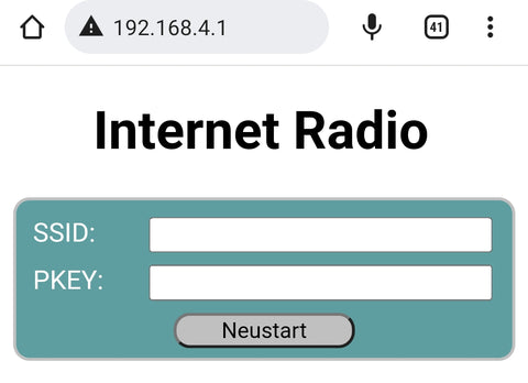
- boolean initWiFi(String ssid, String pkey) Attempts to connect to the local WLAN using the specified credentials. If no SSID is specified or the connection attempt fails, an access point is started. This access point can then be used to access the configuration page from a browser at the address 192.168.4.1.
In order to compile the sketch, the Arduino IDE must be prepared accordingly. The Arduino IDE supports a large number of boards with different microcontrollers by default, but not the ESP32. Therefore, in order to be able to create and upload programs for these controllers, a software package for support must be installed.
First you need to tell the Arduino IDE where to find the additional data it needs. To do this open in the menu File open the item Preferences. In the Preferences window there is the input field called "Additional board administrator URLs". If you click on the icon to the right of the input field, a window will open where you can enter the URL https://raw.githubusercontent.com/espressif/arduino-esp32/gh-pages/package_esp32_index.json can be entered.
Now select the board management in the Arduino IDE under Tool → Board.
A window will open listing all available packages. To narrow down the list, you enter "esp32" in the search field. Then you get only one entry in the list. Install the package "esp32". If the package was already installed, please check if you have the latest version.


Another library is needed for the rotary encoder. Its name is "AiEsp32RotaryEncoder" by Igor Antolic in version 1.4.0.
 But the core of this project is the library "ESP8266Audio" by Earle F. Philhower in version 1.9.7.
 This library allows to read and decode different digital audio streams and play them back over different output channels. As input, the program memory, the internal RAM', a file system, an SD card, an HTTP stream, or an ICY stream can be used. The ICY stream is typically used by Internet radios.
WAV, MOD, MIDI, FLAC, AAC and MP3 files can be decoded. MP3 is required for web radio. Finally, the output can be in memory, files or I2S.
When all libraries are installed, the sketch can be compiled and uploaded to the hardware.
Attention. Since the sketch is composed of numerous parts, compiling can take a long time, especially the first time. In the preferences "Compiler Warnings" should be set to "none", because the LCD library will give a warning by mistake
Commissioning
At the first startup there are no preferences yet. Therefore no connection to the local WLAN can be established. An access point with the SSID "webradioconf" without password is started. A connection to this access point can now be established with a smartphone, for example. Afterwards, the configuration page can be called up in a browser via the address 192.168.4.1.
After the restart, the connection to the local WLAN should be established successfully. The playback of station 0 from the default list (NDR2) should start with a volume of 50%. The volume encoder can be used to set the gain. Changes are saved in the preferences so that the same volume is set the next time the device is switched on. The other encoder can be used to select a station from the list. When turning the encoder, the second line of the display shows the name of the station. By pressing the head on the encoder, the currently displayed station becomes the current station and playback starts. This value is also stored in the preferences. At the next start, the last selected station is automatically played back. If the button on the encoder is not pressed within 10 seconds, the display jumps back to the current station.
Configuration and editing of the station list

The configuration page should be accessible via the URL http://webradio/. In the upper part the access data and the NTP server can be changed. The changes will not take effect until the "Save" button has been clicked.
With the button "Restart" a restart can be triggered.
The drop-down list contains all stations of the station list. Selectable stations have a black dot in front of the name. In the form below, the data for the selected station is displayed and can be changed. If the "Use" check mark is not set, the station cannot be selected in the device. Since some URLs do not work, a new URL should be tested with the "Test" button. Clicking this button starts the playback of the URL on the device. If playback does not work, the device immediately switches back to the current station and displays a message. If playback is possible, a box with a button is displayed. Clicking on this button closes the box and ends the test. The current station is played again. The "Change" button can be used to permanently change the changes for the selected station.
Firmware update via OTA
To update the program it is not necessary to open the device and establish a USB connection. In the Arduino IDE you should see the following entry at the ports.

You can now upload a sketch via this port. For protection, the password "radioupdate" must be entered when prompted. Since the serial port cannot be used, messages are shown on the display.
Notes
The ESP32 has a CPU with two cores. With Internet Radio the web data stream must be read from the Internet via the http protocol. This is done in the system thread running on core 0. The application must decode the received stream and write it to the buffer, from which the data is then output via DMA without CPU intervention. The decoding is done in the application thread running on core 1. If additional CPU time is now used for display and encoder, short interruptions occur that can be heard acoustically when the encoders are turned.
A power supply via the USB bus of the ESP32 module is possible. The supply via the external input is only a recommendation.
The 3D object to the console housing is arranged in such a way that 3D printing is possible without support structures. The link to the print files can be found in the component list at the beginning of the article.
Have fun with the radio!


131 comments
Glenn Foyster
Ich habe dieses Radio zum Laufen gebracht, bis auf ein Problem: Die Zeit zeigt immer noch eine Stunde vor der britischen Zeit an, d. h. der deutschen Zeit und der britischen Sommerzeit. Weiß jemand, wie man das ändern kann?
Ich dachte, es könnte sich ändern, wenn ich einen britischen Sender einschalte, aber das ist nicht passiert.
Ich habe den String NPT auf der Seite webradio_MAX.ino von de.pool.ntp.org in uk.pool.ntp.org geändert, aber keine Änderung.
Hat die Zeit überhaupt etwas mit dieser Einstellung zu tun?
Würde mich über jede Hilfe freuen. Sonst wäre es perfekt. Abgesehen davon, dass die Lautstärke etwas zwielichtig ist und es keine Möglichkeit gibt, das Radio auszuschalten, kann ich die Lautstärke einfach auf Null herunterdrehen!
Glenn Foyster
I have got this radio working except one problem – the time still shows 1 hour ahead of UK time i.e German time and British Summer Time. Does anyone know how to change this?
I thought it might change when I tuned into a UK station but that didn’t happen.
I have changed the String NPT on the webradio_MAX.ino page from de.pool.ntp.org to uk.pool.ntp.org but no change.
Is the time even anything to do with this setting?
Would appreciate any help. Otherwise it would be perfect. Apart from the volume being a bit dodgy and no way of turning the radio off but I can just turn down the volume to zero!
Glenn Foyster
Ich habe dieses Radio erfolgreich aufgebaut und kann die in der Software aufgeführten deutschen Programme einstellen, die gut klingen und auf dem LCD-Bildschirm angezeigt werden. Ich versuche jetzt, die URLs für englische Programme zu finden. Die meisten deutschen Sender scheinen eine MP3-Dateierweiterung zu haben. Für englische Sender kann ich keine MP3-Erweiterungen finden, sondern nur .m4s oder m3u8 oder m3u oder pls.
Ich habe noch keine URLs mit diesen Erweiterungen zum Abspielen. Ist eine Konvertierung in eine MP3-Datei möglich oder weiß jemand, wo MP3-URL-Dateierweiterungen erhältlich sind?
Glenn Foyster
I have successfully constructed this radio and can tune in to the German programmes listed in the software, which sounds good and shows on the LCD screen. I am now trying to find the URL’s for English programmes. Most of the German stations seem to have an mp3 file extension. For English stations I cannot find mp3 extensions but only .m4s or m3u8 or m3u or pls.
I have not got URL’s with these extensions to play yet. Is it possible to convert to an mp3 or does anyone know where mp3 URL file extensions are obtainable
Horst Günther
Das ESP32 Webradio läuft soweit sehr gut, mit LCD2004 als auch mit einem TFT-ILI9488. Nur die eingebettete OTA Funktion ist sehr problematisch und eigentlich nicht zu gebrauchen.
Der Hostname ist in der IDE 1.8. 19 nicht zu sehen, wohl aber in der IDE 2.3.2.
In der 2.3.2 läßt sich der Vorgang auch starten und nach Compilierung beginnt OTA auch zu arbeiten, bricht dann aber ab mit allen 5 OTA Fehlermeldungen.
Ein SW Update mit dem OTAWebUpdater läuft dagegen sicher und wäre vorzuziehen.
Die Frage ist nun, wie kann man die “OTAWebUpdater” Programmzeilen so in die “Index.h” einarbeiten, dass alle Teile (Accespoint-Konfiguration sowie die Webseite für die Radio Konfiguration / Senderlisten und der OTAWebUpdater) laufen können?
Markus
Hallo,
ich habe zunächst die Version aus dem Artikel Internet Radiowecker mit dem AZDelivery Bausatz probiert. TFT funktioniert, Lautsprecher geben nur Brummen ab.
Bei dem obigen Sketch ist mein TFT Display komplett dunkel, Lautsprecher brummen. Serieller Monitor zeigt Verbindung an (“Show Time”).
Gibt es einen Sketch + Schaltplan wo die beiden Encoder angeschlossen sind und die TFT-Platine aus dem Bausatz Internetradio verbaut ist?
Grüße
Markus
Gundbert
Hallo,
ich habe das Radio mit einen ILI9341 Display nachgebaut. Mich stören die Aussetzer während der Display Aktualisierungen. Die Maßnahmen dagegen wurden nur für das LCD gepflegt. Hat jemand hier eine Lösung für das TFT?
Und ich finde es schade, den Bluetooth Empfänger nicht zu nutzen. Die Umschaltung könnte über den nicht genutzten Button des Lautstärkereglers oder als eine Station in der Senderlste erfolgen. Leider reichen meine Kenntnisse nicht um den Code vollständig zu verstehen.
Kamil
Hallo,
just to save time for hobbiest starting project now.
Actual board version esp32 by Espressif System in Arduino IDE is 3.0.0 alfa.
This version produce compiler error and could not be used for this project!
Any previus version is OK.
Dieter
@ Uwe Schmidt vom 13.02.23: Bist du inzwischen mit dem Problem der nur einkanaligen Musikwiedergabe weitergekommen ? Bei mir ist es exakt das Gleiche und das Encoder/Verstärkermodul ist nicht dran schuld. Habe verschiedene erprobt. Es funktioniert immer nur mit einem Modul. Kommt das zweite dazu fängt es an zu krächzen oder/und Audio bricht völlig zusammen. @ Gerald Lechner: Hast du eine Idee???
Gerald Lechner
@Raimund: Es gibt eine Platine, die für alle Varianten verwendet werden kann.
https://aisler.net/p/YSYPXUHW
@Michael Herrmann: Ich nehme an, dass es am Aufbau des Streams liegt. Neben den MP3 Daten werden ja auch Metadaten übertragen.
@Stefan Winkler: Das sollte kein Problem sein. Es sollten noch genug ungenutzte IO-Ports am ESP32 zu finden sein.
Stefan Winkler
Hallo zusammen.
Vielen Dank erstmal für das tolle Projekt.
Die Teile für die Update Version mit dem kleinen TFT sind im Zulauf daher kann ich noch nicht sagen ob oder wie gut das Radio funktionieren wird. Ich habe vor, es fix im Auto einzubauen und es über einen Mobilrouter zu verbinden. Den Lautstärkeregler werde ich nicht nach außen führen sondern innen lassen.
Jetzt die Frage, kann man an das Radio theoretisch 5 Taster anschließen um damit eine Art Memory Funktion zu realisieren? Die Schalter könnten ja sicherlich auf den Programmspeicher zu greifen.
Grüße Stefan
Michael Herrmann
Hallo,
mein erstes ESP32 Projekt ist auf Anhieb gelungen. Ich habe den Code aus dem Projekt “2.Advent aus 2022” minimal geändert (für Audio-Verstärker ohne I2C).
Die Software ließ sich ohne Probleme compilieren.
Hatte zuerst die Version von Herrn Lechner und dann das Update von Herrn Andreas Schröder ausprobiert, was bei der letzteren Version ständig Fehler bzgl. ESPAsyncWebServer brachte.
Nun hätte ich eine Frage:
woran kann es liegen, dass einige URLs mit mp3-Streams nicht abspielbar sind und sofort einen ERROR erzeugen?
Reimund
Hat schon jemand die Platine dafür hergestellt.
Ist bestimmt viel einfacher als alles per Hand zu verdrahten
David S.
@Dirk,
die gleiche Idee hatte ich auch.
Durch drücken des Tasters soll der ESP32 in den Deep sleep, wodurch dann auch ein noch freier pin, der bei ON high ist, auf low geht und damit ein NPN Transistor wegschaltet, der wiederum einen PNP Transistor wegschaltet um die 5V vom Display zu trennen. Dafür bastel ich mir gerade noch eine Schaltung.
Oder hast du einen besseren weg?
Grüße
David
svensche
Hallo Gerald, ich habe mein Problem mit dem 2004 LCD-Display in den Griff bekommen. @AZDelivery Warum schreibt ihr in Eurem eBook zu dem 2004 I2C-LCD, dass man einen Level-Shifter benötigt, wenn man für SDA/SCL 3V3 nutzt?
@Gerald: Ich habe deinen Code in eine Struktur portiert, so dass eine Entwicklung mit VSCode/PlatformIO möglich ist – https://github.com/chess-levin/esp32webradio
@All: Freue mich über Ergänzungen, Verbesserungen etc.
Svensche
Hallo Herr Lechner,
großartiges Projekt – dankeschön!!!!
Ich habe mir die letzte Nacht um die Ohren geschlagen, weil ich das HD44780 2004 LCD Display Bundle 4×20 Zeichen mit I2C Schnittstelle Blau am ESP32 nicht zum Laufen bekomme. Ich habe es als einziges Device an Pin 21,22, +5V, GND am ESP32 angeschlossen. Hatte zuerst die SDA/SCL direkt an den die Ports 21/22 angeschlossen, dann habe ich das AZ-eBook gelesen und einen Levelshifter dazwischen geklemmt. Hatte aber nicht den im eBook genannten TXS0108E sondern einen “mmtrade | 3x 4-Kanal Pegelwandler Logic Level Converter Shifter 4 Kanal Pegelwandler I2C IIC BiDirektional 5V~3.3V für Arduino Raspberry Pi Mikrocontroller” (https://www.amazon.de/Converter-Pegelwandler-BiDirektional-Raspberry-Mikrocontroller/dp/B07DKT9JXT/ref=asc_df_B07DKT9JXT)
Der Demosketch von https://github.com/iakop/LiquidCrystal_I2C_ESP32/blob/master/examples/HelloWorld/HelloWorld_ESP32.ino compiliert (habe die I2C Pins auf 21/22 geändert). Die Hintergrundbeleuchtung des Displays leuchtet, aber es werden keine Zeichen angezeigt.
Ich habe auch diverse andere LCD Libs probiert, aber die Anzeige von Zeichen funktioniert nie. Hat jemand einen Tipp für mich…?
dirk
Ich hätte da noch einen Verbesserungsvorschlag:
der Taster am Lautstärkeregler ist ja noch ungenutzt, wie wäre es, diesen zu benutzen um das Gerät (sowohl den ESP32 als auch das Display) durch Drücken dieses Tasters in den Standby zu schicken und ihn durch nochmaliges Drücken wieder aus dem Standby aufzuwecken. Das sollte eigentlich kein großes Problem darstellen, erfordert aber eine kleinere Modifikation der Schaltung und auch der Software…
Das würde dann auch wieder den Akkubetrieb ermöglichen.
Zum anderen wäre es dann auch möglich über das Webinterface einen Timer zu Programmieren um seine Lieblingssendung nicht zu verpassen…
LG, dirk
David
Hallo,
Ich würde mir auch gerne ein Radio aufbauen, gibt es auch für die Version mit Farbdisplay auch eine 3D Datei?
Grüße
David
Mirko Jacke
kann mir jemand einen tipp geben, warum mein esp nicht in der fritzbox erkannt wird, bis auf das verbinden mit dem ap lief alles super
Bernhard Rekemeier
Berechnung: ?
5 / (4,7+10) x 4,7 = 3,4 # nö
5V / (4,7k+10k) x 4,7k – 5V = 3,4V # ja
Jeder ESP- Dev. hat einen Spannungsregler von 5V auf 3,3 V. Also sollten die GPIOs auch auf 3,3V laufen. Wo 5V draufsteht, sollte auch 5 V vorhanden sein, z.B. BME280 Sensor, den es in 5V und 3,3V gibt. Ich arbeite ausschließlich mit 3,3 V auf den ESPs, bisher ohne Probleme. Auch an die 10k Widerstände (3,3V an SDA) denken, wenn der I2C-Bus mit mehr Devices verwendet wird(Display und Sensor).
Pit
@Gerald Lechner
Falsch, ich habe nicht “im Prinzip” recht sonder meine Aussage ist eindeutig richtig,
weder der ESP8266 noch der ESP32 ist 5V telerant. Das etwas gerade geht OBWOHL es technisch falsch ist macht es nicht besser. Ihre vorgeschlagene Loesung
<
Die Pullup Widerstände sind 4,7kOhm. wenn man beide Leitungen über 10kOhm mit Masse
verbindet ändert sich die Leerlaufspannung von 5V auf 3.4 V. Spannungsteiler 5 / (4.7 + 10) * 4.7 = 3.4
>
Ginge natuerlich auch.
Ich bin halt der Meinung man sollte in Schaltungsvorschlaegen technisch sauber arbeiten damit Menschen die etwas nachbauen sich nicht falsches merken, denn in einer anderen Kombination von Modulen mit dem ESP koennte derartiges ihn zerstoeren.
Gerald Lechner
@Pit: Sie haben im Prinzip recht. Da beide Signalleitungen vom ESP32 als Ausgang betrieben werden ist es aber nicht ganz so kritisch. Ich hatte noch keine Probleme damit.
Die Pullup Widerstände sind 4,7kOhm. wenn man beide Leitungen über 10kOhm mit Masse
verbindet ändert sich die Leerlaufspannung von 5V auf 3.4 V. Spannungsteiler 5 / (4.7 + 10) * 4.7 = 3.4
Pit
Hi
Hier das gleiche Problem wie bei der urspruenglichen Variante:
ich finde die Anschaltung des Display es etwas “gefaehrlich” fuer den ESP32,
denn so wie dargestellt wird der I2C ueber die PullUps auf der Display-Interfaceplatine
auf 5V gezogen, der ESP32 mag aber , soweit mir bekannt , keine 5V am GPIO.
Deswegen wuerde ich vorschlagen entweder das Display auf 3V3 oder die PullUps
von der Interfaceplatine entfernen und 2 neue gegen 3V3 in die Schaltung zu integrieren.
Michel
@Hans-Jürgen
https://github.com/adafruit/Fritzing-Library/blob/master/parts/Adafruit%20MAX98357A.fzpz
Hans-Jürgen
Moin,
kann mir jemand einen Tip geben, wo ich das Fritzing-File für den Verstärker MAX98357A finde?
Ich möchte versuchen, eine Platine für das Wlan-Radio mit dem TFT-Display zu erstellen.
Danke schon mal
Hans-Jürgen
Rainer
Hat schon jemand die Platine dafür hergestellt. Wenn ja würde ich gerne gegen Unkosten erstatten, diese erstehen.
Mfg Rainer
Rainer
Läuft prima. Etwas friemelig war der Zusammenbau mit dem 4x 20 Zeilen Display. Wenig Platz um die Lautsprecher fest zu schrauben. Aber nun funktioniert alles.
Wumba
Nochmal ein Repost, weil ich mal weider drüber gestolpert bin: Stottern kommtn, wenn der 10 k Widerstand am GPIO 35 zum 3,3 V Anschluss fehlt.
Warum ist das so?
#Stottern#Abbruch#Aussetzer
Konrad
Hallo beisammen,
Kleine Frage an Alle: Hat jemand das mit der SD-Card mal ausprobiert und die jeweiligen mp3 Musikdateien “angespielt”? Habe noch nicht das TFT Display ausprobiert und würde mich einfach mal interessieren, wie man die Karte musiktechnisch über die Knöpfe ansteuert.
Auch war irgendwo mal die Idee zu einem Radiowecker. Gibt es dazu schon Ansätze?
Danke
Konrad
Kamil
Thank you Mr. Lechner for precise answer. Now it is OK.
Just the last question concerning special characters. In the software subpart “display”, there is code on the first about 50 lines for german characters.
(How to display them on dot 8×8 and than if such character is detected which display pattern should be used).
I have tried to use those functions to display some my language characters. For example: é. (e with acute), Dec. code is 195 169. If I put all data inside functions, I was not succesfull. The result was e without any sign over it. I have tried to see original Titel for song through Serial monitor, Titel in my language was without acute?
I suppose: some special characters are not even transfered by internet? I could not compare with German
station, because few choosen German stations displayed names of English songs only without special german characters.
Can you advice how to display special not german characters?
Gerald Lechner
@Kamil: This problem occurs if you missed the 10k resistor from 3.3V to GPIO35. This resistor is always required even if the rotary switch for station selection is not supplied.
Konrad
@Tommy: Großes Dankeschön. Tolle Arbeit.
Thommy
Hallo zusammen,
ich habe das Gehäuse eben bei Thingiverse veröffentlicht. Es sind STL Dateien, sowie auch die SCAD Dateien zum Download verfügbar. (Damit ihr das Modell ggf. anpassen könnt. Die Einschmelzmuttern M3 findet ihr bei Amazon oder bei Ebay. Dort gibt es Sets die aus Einschmelzmutter und Schraube besteht. Alles hält damit noch besser und es wird auch nix lose mit der Zeit, als wenn man nur Schrauben in den Kunststoff schraubt. Ich nutze diese für all meine Projekte und habe damit sehr gute Erfahrungen gemacht. Vielleicht noch einen Tip beim Drucken der Beschriftungen – ich habe hierfür bei Cura einen Filamentwechsel eingestellt, damit er ab einer bestimmten Höhe nicht mehr blau sondern weiß druckt. Wem das zu umständlich ist, der druckt einfarbig und malt die Konturen mit einem weißen Edding(oder besser weißen Acrylfarbstift) nach. Und wer sicht fragt warum das Radio “No. 7” heißt; das ist mein 7. Radio was ich gebaut habe.(nicht immer das gleiche, sondern eigene Projekte)
So genug gesabbelt – Viel Spaß beim nachdrucken. ;-)
Hier gehts zum Gehäuse: https://www.thingiverse.com/thing:5954124
Kamil
To make more clear what is " pulsating sound": Sound is ON for about 0.5s, than OFF for 0.5s, than ON, than OFF and so on, like modulated by rectangular pulses 1Hz (not 0.5Hz). Does not matter which web station is selected.
Kamil
Hallo,
very nice project and clear software.
But I have a problem with sound:
Compilation and upload is O.K.
Display is 4×20 original AZ Delivery. Esp32 is 30 pins.
Display is working, but after WiFi is connected, there is sound pulsating in frequency about 0.5 Hz, Volume is O,K.
If there is not pulsation, sound looks good.
I simplified hardware for just ESP32 and one Max amplifier. Sound was pulsating again.
Than I loaded other very simple software. Sound was OK. It means, that problem could be in software?
I have check project with external power 5V, but results are the same.
I have tried to adjust SD pin by resistor to different modes, no influence.
Multimeter show me some pulsation on pin 27 of ESP32.
Can you advice,
best regards
Kamil
Günter
Kanal-/Lautstärke-Fehler gefunden, es war die Zeile 40 in der audio.ino (out = new AudioOutputI2S(0,1);). Obwohl ich die Zeile im sketch gemäß Hinweisen geändert hatte, hat die IDE immer die falsche Version geladen (mein Fehler: das Archiv existierte zuerst noch ausgepackt in /Downloads,) Es ist nicht das erste Mal, dass ich an der 2.0-IDE verzweifle). Auch wenn der Compiler nichts beanstandet, lohnt es sich also, den Output durchzulesen. Das Löschen des entpackten Archivs in /Downloads war die Abhilfe. Nun ein schönes begeisterndes Gerät geworden, vielen Dank.
Günter R..
Siegfried
@ Günter R : ich habe die Audio Bibliothek auf Version 1.9.5 und damit läuft es stabil und gut. ESP32 Version ist dabei 2.0.6
Gruß
Günter R.
Herzlichen Dank an Herrn Lechner zuerst, für einen wirklich vollständigen Projekt-Umfang. Auch hier läuft fast alles auf Anhieb, denn leider bekomme ich nur auf einem Kanl und dort stark verzerrtes pumpendes Audiosignal (auf allen Sendern übrigens). Die Audio-Biblithek ist Version 1.9.7. Gibt es Erkenntnisse, dass eine ältere Version diesen Fehler vielleicht noch nicht haben könnte? Vielen Dank im Voraus…
Konrad
@Thommy: Hier, hier, hier!! Sieht echt toll aus. Bitte gerne die slt Dateien, bzw. CAD. Großes Dankeschön
Kleine Frage an Alle: Hat jemand das mit der SD-Card mal ausprobiert und die jeweiligen mp3 Musikdateien “angespielt”? Habe noch nicht das TFT Display ausprobiert und würde mich einfach mal interessieren, wie man die Karte musiktechnisch über die Knöpfe ansteuert.
Danke
Konrad
Dank
Rainer Hoffmann
@Thommy
Ein sehr schönes Gehäuse hast du da entworfen. Ich bin interessiert!
Thommy
@Sven
Doch es könnte tatsächlich am Code liegen. Schau mal bitte in der webradio_MAX_TFT.ino Datei nach. Dort findest du folgende Zeile:
“bool newTitle = false;”
Diese Zeile ist muss aber auf true gesetzt werden, da sonst keine Titel angezeigt werden.
Also die Zeile wie folgt abändern:
“bool newTitle = true;”
Danach bloß noch auf deinen ESP32 flashen und es sollte funktionieren.
Bitte auch noch in der audio.ino Datei nachsehen. Dort gibt es die selbe Zeile. Die sollte auch auf “true” stehen.
Thommy
Ich habe die Version mit dem 1.8er Display und der Platine von Herrn Lechner nachgebaut. Das Gehäuse hat mir nicht ganz so gefallen, deswegen habe ich ein eigenes konstruiert. Die beiden Knöpfe und die Schriftzüge natürlich auch. Für die Befestigung der Platine, der Lautsprecher und dem Deckel habe ich Einschmelzgewinde M3 genommen.
https://photos.app.goo.gl/EvanbvWFKMPprEx79
Wenn Interesse am Gehäuse besteht kann ich es gern kostenlos zur Verfügung stellen. Ich habe es mit openscad konstruiert, sodass man es leicht anpassen kann.
Sven Laur
@Siegfried: Danke für Deine Antwort. Bei mir zeigen auch die von Dir erwähnten Sender keine Titelinformationen an. Hat jemand eine Idee wie man hier am besten nach dem Fehler suchen kann? Am Code wird es sicher nicht liegen, wenn andere die Infos angezeigt bekommen. Am Display liegt es auch nicht da ich die Variable „Titel“ über den seriellenMonitor ausgegeben habe und dort auch kein Inhalt vorhanden war. Kann man die Titelinfos auch mit einem anderen Programm auslesen um das mal zu testen? Bin für jeden Hinweis dankbar denn irgendwie wurmt mich das, dass mein halbes Display leer bleibt. :-)
Siegfried
@ Sven Laur: bei mir zeigen auch nicht alle Sender diese Titel an, aber z.B. MDR oder NDR oder Antenne Bayern liefern diese Info und dann sehe ich diese auch auf dem Display ( habe das 2.8“Display )
Gruß
Siegfried
@Klaus : zum Display ILI 9341
https://radio-bastler.de/forum/showthread.php?tid=21930&highlight=azdelivery
Im Radio-Bastel-Forum hat der Jupp diese Änderung sehr gut beschrieben. Allerdings muss man sich da anmelden. Es lohnt sich, weil es da auch noch viele Vorschläge gibt, wenn man ein Gehäuse dazu benötigt.
Torsten Krämer
@ Siegfried: Verdammte Tat – der Kontakt am Widerstand war mau…. Es war genau das Thema – Danke Dir . Es zeigt mal wieder nicht machen → richtig machen ….. Danke !
Torsten Krämer
@Siegfried: Servus, das Thema 10 k hatte ich irgendwo schon gelesen, keine Idee wo , sorry. darum habe ich das ganze Radio einmal genau wie in der Beschreibung aufgebaut inkl. der Endstufen für Lautsprecher. Ich benötige eigentlich nur Line out, wollte aber möglichst jede Situation ausschließen. Leider identischer “Erfolg”. Meine letzte Idee ist aktuell das es am verwenden ESP32 Board liegen könnte (?). Leider aktuell bei Az nicht verfügbar. Ich hatte einen alternativen Lieferanten probiert. Ist das überhaupt mehr als eine theoretische Option? Gerne Eure Meinung und Anregungen aller Art. Stottern ist nach wie vor da. Grüße Torsten
Sven Laur
Hallo Zusammen,
sehr schönes Projekt, höre gerade in meinem Bastelkeller über WLAN glasklar Musik. :-)
Gibt es schon eine Idee warum die Titelanzeige nicht funktioniert? Hat jemand diese Anzeige?
Ich nutze die Version mit dem TFT Display (webradio_MAX_TFT)
Ich habe in die Funktion MDCallback mal ein Serial.println eingefügt, aber das meldet sich nicht.
Daher gehe ich mal davon aus das die Funktion nicht aufgeführt wird.
Bei der Programmzeile "file→RegisterMetadataCB(MDCallback, NULL); " im Teil audio.ino Teil bin ich raus. Das übersteigt meine bescheidenen Programmierfähigkeiten. Aufgerufen müsste die Zeile aber nach meiner Meinung werden da die etwas weiter unten programmierten Meldungen auf dem Seriellen Monitor kommen. Kann mir hierbei jemand helfen? Vielen Dank.
klaus
Hallo
ich habe mit Erfolg beide Varianten des Projektes nachgebaut. Auch ohne viel Erfahrung mit der Programierung des ESP`s
Vielen Dank für das Projekt.
Jetzt habe ich aber ein Problem. Da ich auch ein TFT Display 2,4 " ILI9341 noch habe wollte ich dieses in dem Projekt verwenden. Nach runterladen und aufspielen des TFT Codes auf den ESP erhalte ich natürlich nicht die exakte Display Anzeige weil ein anderes Display programmiert ist.
Jetzt meine Frage: Wo und was muss ich ändern im Code kann mir da jemand vielleicht helfen.
Das Radio funktioniert schon auch das Display zeigt die richtigen Werte und Symbole an. Nur etwas zu klein für das Display und gespiegelt ist es auch.
Siegfried
@ Torsten Krämer bei mir gibt es solch Reaktion, wenn der 10 k Widerstand am GPIO 35 zum 3,3 V Anschluss fehlt (Encoder Sender SW muss ja nicht unbedingt angeschlossen sein)