
This post is also available as PDF document available.
With the ESP32 you can paint. My paintbrush is a program written in MicroPython, the canvas consists of a LED matrix, equipped with 256 neopixel LEDs. And while painting, the controller drives a sound module that plays songs from an SD card. Every hour, a song is selected by a random generator. To make sure the time is correct, the ESP32 synchronizes its system time with a time server on the Internet. Curious now? Then join me in the virtual painting studio with a new episode of
MicroPython on the ESP32 and ESP8266
today
Christmas pictures and music with the ESP32

Image 1: Minimalistic circuit
The circuit gets along with five parts, so it is very clear. The two active components are an ESP32 and a DF-Player Mini. The former needs two breadboards because of its wide design, so that all legs of the 38-footer can have a home. The controller is powered by the USB cable, or later by a 5V power supply. This should be able to supply currents up to about 2 amps, because the LEDs of the matrix draw about 30 mA each at full luminosity of the red, green and blue LEDs. If all 256 LEDs are at full power, then the panel swallows a whopping 7.5A. But don't worry, the images we'll generate will stay well under an amp if we're only running at 20% power. Believe me, that's bright enough.
But first, here's the schematic.

Image 2: Circuit diagram
The DF player also lives on one of the breadboards. The songs are located as MP3 or WAV files on a mini SD card, which may have up to 4 GB of storage space. On it, up to 255 files each can be placed in up to 100 folders and addressed directly. The names of the folders must be of the form 00 ... 99, the file names always start with three digits. Other alphanumeric characters may follow. A dot separates the name from the name extension. For this purpose .MP3 or .WAV can be used. A valid file name could be for example 003_Vom_Himmel_hoch.MP3. The card can be FAT16 or FAT32 formatted. The sampling rate of the files must be one of the following:
-
8 KHz
-
11.025 KHz
-
12 KHz
-
16 KHz
-
22.05 KHz
-
24 KHz
-
32 KHz
-
44.1 KHz
-
48 KHz
The DF-Player is controlled via a RS232 connection. The default settings are 9600 baud, 8 bit, no parity, one stop bit. For bidirectional operation an ESP32 is necessary, because the ESP8266 provides only one TX line at UART1. Furthermore, the little brother of the ESP32 is quite narrow in terms of system memory.
The data sheet of the DF-Player serves the reader with a rather idiosyncratic English. Most of the commands that can be sent to the chip are listed there. I made a MicroPython module out of it, which saves you the trouble of having to code the commands to the DF-Player yourself. But if you want to go deeper, it's worth to have a look at the file dfplayer.py in any case.
Hardware
|
1 |
ESP32 Dev Kit C V4 unsoldered or ESP32 NodeMCU Module WLAN WiFi Development Board with CP2102 or |
|
1 |
|
|
1 |
|
|
1 |
|
|
1 |
|
|
Possibly |
Base board 17cm x 17cm |
The software
For flashing and programming the ESP32:
Thonny or
Used firmware for the ESP32:
The MicroPython programs for the project:
dfplayer.py Hardware driver for the DF-Player mini
pictures.py The master painter
MicroPython - Language - Modules and programs
For the installation of Thonny you find here a detailed manual (english version). In it there is also a description how the Micropython firmware (as of 18.06.2022) on the ESP chip. burned is burned.
MicroPython is an interpreter language. The main difference to the Arduino IDE, where you always and only flash whole programs, is that you only have to flash the MicroPython firmware once at the beginning to the ESP32, so that the controller understands MicroPython instructions. You can use Thonny, µPyCraft or esptool.py to do this. For Thonny, I have described the process here described here.
Once the firmware is flashed, you can casually talk to your controller one-on-one, test individual commands, and immediately see the response without having to compile and transfer an entire program first. In fact, that's what bothers me about the Arduino IDE. You simply save an enormous amount of time if you can do simple tests of the syntax and the hardware up to trying out and refining functions and whole program parts via the command line in advance before you knit a program out of it. For this purpose ,I also would like to create small test programs from time to time. As a kind of macro they summarize recurring commands. From such program fragments sometimes whole applications are developed.
Autostart
If you want the program to start autonomously when the controller is switched on, copy the program text into a newly created blank file. Save this file as boot.py in the workspace and upload it to the ESP chip. The program will start automatically at the next reset or power-on.
Test programs
Manually, programs are started from the current editor window in the Thonny IDE via the F5 key. This is quicker than clicking on the Start button, or via the menu Run. Only the modules used in the program must be in the flash of the ESP32.
In between times Arduino IDE again?
If you want to use the controller together with the Arduino IDE again later, simply flash the program in the usual way. However, the ESP32/ESP8266 will then have forgotten that it ever spoke MicroPython. Conversely, any Espressif chip that contains a compiled program from the Arduino IDE or the AT firmware or LUA or ... can easily be flashed with the MicroPython firmware. The process is always like here described.
Signals on the RS232 and Neopixel bus
How a transmission on the RS232 bus runs and how the signal sequence looks like, you can see by a interesting little tool with which you can get the bus signals on your PC and analyze them. The operation of the Logic Analyzer is in Mammoth Matrix Display with MAX7219, ESP8266/ESP32 and GY-21 in MicroPython - Part 2 described. However, do not clamp the measurement strips to the SCL and SDA but to the RX and TX lines. Of course you can also use the tool to visualize the signals you send to the LED panel. Both bus systems are based on a specific protocol. I have described the functionality of Neopixel LEDs in Bandit - Games with the ESP32 in MicroPython described before. About the RS232 interface I wrote in the article "Chat with the PC - the RS232 interface" I have compiled information about the RS232 interface.
The master painter
The program for controlling the LEDs is modular. All four pictures are realized by means of functions. This makes it easy to change or extend the existing structures and to add new ones. Irregular images like the star are best created in the form of lists. The list elements for their part are Tuples with the position numbers of the LEDs. The sequential data type List is defined by square brackets, a tuple by round brackets.
family=[
     (120,121,136,137), # 0
     (103,106,151,154), # 1
     (86,91,166,171), # 2
     (52,69,70,85,87,102,
     90,107,75,92,76,61,
     150,167,165,182,181,196,
     170,155,172,187,188,205), # 3
     (88,89,104,105,
     122,123,138,139,
     152,153,168,169,
     118,119,134,135), # 4
     (18,35,36,51,53,54,68,71,84,101,
     31,45,46,59,60,62,74,77,93,108,149,
     183,164,180,197,198,195,211,212,226,
     156,186,173,203,204,189,206,221,222,239), #5
     (40,56,57,72,73,
     124,125,126,140,141,
     184,185,200,201,217,
     116,117,131,132,133), # 6
     (1,2,17,19,20,34,37,38,50,55,67,83,100,
     58,43,44,29,30,15,16,32,47,63,78,94,109,
     157,174,190,207,223,240,256,255,237,238,220,219,202,
     199,213,214,227,228,241,242,225,210,194,179,163,148), # 7
     (8,24,25,41,
     127,128,142,143,
     216,232,233,249,
     114,115,129,130) # 8
    ]

Image 3: Poinsettia
The color palette of the star is also a list. The Tuples contain the color components for red, green and blue.
factor=0.5 # Brightness factor
color=[(32,0,8),
       (64,0,2),
       (96,0,0),
       (128,16,0),
       (128,32,0),
       (128,48,0),
       (128,72,0),
       (128,128,0),
       (128,128,32),
       (128,128,64),
       (128,128,96),
       (128,128,128),
       (192,192,192)
      ]
Other images are built using functions that set pixels, draw rectangles or create fills.

Image 4: Advent candle large
But, everything in order. Like every MicroPython program, this one starts with a few imports. After that the objects are created.
from machine import Pin, RTC
from time import sleep, time, localtime, ticks_ms
import ntptime
from neopixel import NeoPixel
from sys import exit
import network, socket
from dfplayer import DFPlayer
import random
Except for the module dfplayer all others are already included in the MicroPython package. dfplayer.py has to be uploaded extra to the ESP32 before you can import the module. So download the file and copy it to the working directory of Thonny.

Image 5: Files in the working directory
Click dfplayer.py with the right mouse button and select from the context menu Upload to /.
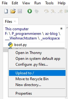
Image 6: Upload file
Now the file should be in the flash of the ESP32.

Image 7: Uploaded file
I create a Neopixel instance that controls the panel via GPIO5. The object provides a list as a data buffer. Each element contains the three color information in the form of a Tuple.
neo=5 # D3
neoPin=Pin(neo,Pin.OUT)
neoCnt=256
np = NeoPixel(neoPin, neoCnt) #
To ensure that date and time are correct, the internal clock, the Real-Time-Clock (RTC), of the ESP32 must be synchronized regularly with the time stamp of a time server on the Internet. The time span in which this happens is defined by syncInterval defines.
syncInterval=600000 # ms
We are in Europe in the time zone where one hour to the UTC (Universal Time Coordinated) is added. I specify the hours in which my panel should be active along with playing music by specifying a range in the variable hours variable.
timeZone=1
rtc=RTC()
rtcTag=(2022,11,27,6,8,0,0,0) # RTC day stamp start
# year,month,day,hour,minute,second,day of week,anniversary
hours=range(8,23)
To access an NTP server we need the WLAN. The access parameters for the SSID and the password depend on the settings of your WLAN router. So be sure to enter your own credentials here. The port number, on the other hand, is almost freely selectable and may be between 1024 and 65535.
# **************Define WLAN access*******************
#
mySSID="Here goes your SSID"
myPass="Here goes your password"
myPort=9009
The network interface (nic) of the ESP32 returns various status messages when a connection is established. The dictionary (aka Dict) connectStatus translates the numeric codes into plain text.
connectStatus = {
    1000: "STAT_IDLE",
    1001: "STAT_CONNECTING",
    1010: "STAT_GOT_IP",
    202:  "STAT_WRONG_PASSWORD",
    201:  "NO AP FOUND",
    5:    "UNKNOWN",
    0: "STAT_IDLE",
    1: "STAT_CONNECTING",
    5: "STAT_GOT_IP",
    2:  "STAT_WRONG_PASSWORD",
    3:  "NO AP FOUND",
    4:  "STAT_CONNECT_FAIL",
    }
Like the values in a tuple, the keys in a dictionary (dict for short) are immutable; they cannot be changed after the structure has been declared. While keys of a tuple must be unique, values may occur more than once. Dicts are enclosed by curly braces. Key and value are separated by a colon. There is a comma between the pairs, as between the elements of a list.
A large part of the program work is done by functions. The function hexMac() is one of them and translates the program code generated by the method nic.config() method into a human-readable string. This string consists of the usual hexadecimal digits 0-9 and A-F, through which the MAC address of the station interface (STA) of the ESP32 is defined.
This six-pack must be made known to the WLAN router so that it grants access to the ESP32. To do this, the address must be added to the list of authorized devices. You can usually find this in the maintenance menu of your router under the item WLAN - Security. For the exact procedure please consult the manual of your device. By the way, for security reasons, it is not a good idea to generally allow access to all devices that log in by turning off MAC filtering. The next hacker will be very happy if you keep all doors open for him.
def hexMac(byteMac):
  """
  The hexMAC function takes the MAC address in bytecode and
  forms a string for the return
  """
  macString =""
  for i in range(0,len(byteMac)):     # For all byte values
    macString += hex(byteMac[i])[2:]  # String from 2 to end
    if i <len(byteMac)-1 :            # separator
      macString +="-"                 # except last byte
  return macString
The core cell of the program pictures.py is to set the color of a pixel, the function setPixel(). It takes the color codes for red, green and blue as position parameters in addition to the LED unit number. It is followed by the parameter fwhich defines the brightness of the pixel. The value ranges from 0.0 to 1.0. The parameter show defines with the default value Truethat the change is immediately transferred to the panel. If it is set when calling the function with False when the function is called, then the change is not made until the True of a subsequent, corresponding function call or by calling the function show().
def setPixel(num,r,g,b,f,show=True):
    z=(num // 16) + 1
    n=num if z % 2 == 0 else z*16 - (num % 16 + 1)
    r=int(r*f)
    g=int(g*f)
    b=int(b*f)
    np[n]=(r,g,b)
    if show:
        np.write()
        sleep(0.01)
An insertion is needed here. I had originally assumed that the addressing of the cells of the panel would be oriented from left to right and line by line from top to bottom, corresponding to an x-y coordinate system. Unfortunately, this was not the case. According to my orientation of the panel, the passing of the addresses happens in the first line from the top right, pixel 0, to the top left, pixel 15, and then in the second line from the left, pixel 16, to the right, pixel 31, and following the snake line downwards.
But the image was just designed according to the x-y system. I used Libre Office Calc for this purpose. The figures 7 and 8 show the connection, which is made in the following lines.
    z=(num // 16) + 1
    n=num if z % 2 == 0 else z*16 - (num % 16 + 1)
All higher functions for illuminating pixels access setPixel().
Image 8: Libre Office x-y system

Image 9: Libre Office snake system
Functions with broad effect are showColors() and especially clearPanel(). The former shows the colors available for the star, clearPanel() should actually make all LEDs go out. However, a strange effect appeared already in the early development phase of the program. Instead of clearing all LEDs (code = (0,0,0)) some of them lit up in different colors and brightness levels. Position and brightness varied and still do. Which phenomenon is behind this, I could not discover until now. So every time the write function is accessed, the following flares up np.write(), completely uninvolved LEDs suddenly flare up. If you know a remedy for this, I look forward to your comment on this post.
def showColors(fak):
clearPanel()
for col in range(len(color)):
r,g,b=color[col]
setPixel(col,r,g,b,fak)
def clearPanel(show=True):
for i in range(neoCnt):
np[i]=(0,0,0)
if show:
np.write()
sleep(0.01)
The function fill() fills the pixels from address from to address until in the specified color of the T uple col with the brightness factor fak shine.
def fill(from,to,col,fak,show=True):
    for n in range(from,to+1):
        setPixel(n,col[0],col[1],col[2],fak,show)
A similar function has rectangle() has a similar function. It fills the pixels from the serial position n in a width of b and a height of h in which, in col coded color with the factor fak adjusted brightness.
def rectangle(n,b,h,col,fak,show=True):
    red,green,blue=col
    for y in range(h):
        for x in range(b):
            setPixel(n+x+16*y,red,green,blue,fak,show=True)
The function show() brings hidden changes to the buffer memory of the object npthat were not initiated with the corresponding functions (show=False).
def show():
    np.write()
    sleep(0.01)
The function wreathcandle() builds a candle for the advent wreath, which is used in the function wreath() function. The attribute n identifies the pixel in the coordinate system where the lower left corner of the candle should be.
def wreathcandle(n,col,fak):
    f=n-32-2*16
    rectangle(n-2*16,2,3,col,fak)
    rectangle(f,2,2,(128,72,0),fak)
    setPixel(f-16,128,96,0,fak)
    setPixel(f-32+1,128,128,0,fak)
def wreath(fak):
    fill(0,223,(0,0,32),fak)
    fill(224,255,(16,16,0),fak)
    rectangle(177,14,3,(9,128,0),fak)
    for n in (162,166,169,172):
        wreathCandle(n,(128,0,0),fak)
        sleep(1)

Image 10: Advent wreath with candles
The function wreathcandle() is called by wreath() is called. wreath() creates a rectangle that is populated with candles. It appears in front of a blue background, which is filled with the function fill() function.
The function tree() creates the image of a Christmas tree - with candles. It makes use of the function layer(), which builds up the individual layers of the tree. Thereby n here is the number of the pixel in the layer at the bottom left. The width follows b of this bottom row and the height h.
def layer(n,b,h,fak):
    for y in range(h):
        for x in range(b-2*y):
            pos=n-y*16+y+x
            setPixel(pos,0,128,0,fak)
def tree(fak):
    fill(0,255,(0,0,32),fak)
    rectangle(231,2,2,(8,8,0),fak)
    layer(210,12,4,fak)
    layer(147,10,4,fak)
    layer(84, 8,4,fak)
    layer(37, 4,2,fak)
    for p in (40,54,89,74,118,152,181,202,211,215,220):
        treeCandle(p,(128,128,0),fak)
        sleep(1)

Image 11: Tree with candles
The function candle() builds from the geometric basic elements fill(), rectangle() and setPixel() will set the image of a candle.
def candle(fak):
    fill(0,255,(0,0,32),fak)
    rectangle(226,11,2,(16,16,0),fak)
    rectangle(116,7,7,(128,0,0),fak)
    for p in (84,100,101,106):
        setPixel(p,128,0,0,fak)
    for p in (84,100,101,106):
        setPixel(p,128,0,0,fak)
    for p in (70,71,72,87):
        setPixel(p,128,32,0,fak)
    for p in (55,56):
        setPixel(p,128,64,0,fak)
    for p in (38,39):
        setPixel(p,128,128,0,fak)
    for p in (7,23):
        setPixel(p,128,128,32,fak)
The structure of the star is considerably more complex than the previous images. Nevertheless, the definition of its outfit leads through the functions star() and showFamily() via the list family to a surprisingly short code in the functions.
def showFamily(n,col,fak):
    for pos in family[n]:
        r,g,b=color[col]
        setPixel(pos-1,r,g,b,fak)
The star is like an ogre, and ogres are like onions, they have shells (Ohh Shrek!). I call the shells Families. The function showFamily() now brings up exactly one shell whose number is specified in n will be displayed in the color that is specified in the tuple col tuple.
The function star() first builds up the image to subsequently change the color of the shells once again.
def star(fak):
    for fam in range(10):
        for frame in range(fam):
            showFamily(frame,fam-frame,fak)
    for col in range(9,13):
        for fam in range(9):
            showFamily(fam,13-(col-fam),fak)
Depending on whether a WLAN is available, the function gives getDayTime() returns a tuple with the current date and time. With network access the function gets the information from the system time of the ESP32. This is read in intervals, which are defined by the variable syncInterval in milliseconds, by contacting a time server. More about this in a moment.
syncInterval=600000 # ms
If there is no network access, then the Real Time Clock (RTC) of the ESP32 is used. Of course the RTC has to be adjusted first. For this the variable rtcTag is responsible.
rtcTag=(2022,12,14,8,23,12,0,0) # RTC day stamp start
# year,month,day,hour,minute,second,day of week,anniversary
The 8-tuple is supplied with the start time data before the program starts. The sorting of the RTC record is different from that of the system time (for whatever reason?), and therefore the fields need to be reordered.
def getDayTime():
    if nic.status() in (5,1010):
        return localtime(time()+timeZone*3600)
    yr,mon,day,dow,hor,minute,sec,ms=rtc.datetime()
    return(yr,mon,day,hor,minute,sec,dow)
The function TimeOut() is something very special. It does not return a value, which functions sometimes do (see getDayTime()), but the function compare(), which is defined in the function body. Strictly speaking, it is not the function that is returned, but a reference to it. Everything that is declared inside a function in terms of objects and variables is local with respect to the function and cannot be referenced outside the function, i.e. it is quasi unreachable. If the function is exited, all locally defined objects die. This is done with TimeOut() by the fact that the function defined inside the compare() is applied to the parameter t and the outside of compare(), defined to TimeOut() local variable start accesses. From the function TimeOut() function becomes a so-called Closure.
This pull-up allows me to include as many easy-to-manage software timers in my programs as I want. Each timer works independently from the others in the background, so it does not block the program flow in any way. Only when calling the reference to the returned function, it wakes up from its slumber and returns the information whether the timer has expired or not. Unfortunately, this type of timer is not interrupt-capable. With TimeOut() cannot interrupt a running program by an interrupt request (IRQ = Interrupt Request) and therefore must be polled repeatedly.
def TimeOut(t):
    start=ticks_ms()
    def compare():
        return int(ticks_ms()-start) >= t
    return compare
After filling the toolbox with objects and functions we now get to work. First we try to connect the ESP32 to the network. For this we need the station network interface (STA). So that the access point interface doesn't interfere, which is often the case with the ESP8266, I first choke it off safely. Then I instantiate the STA interface and activate it.
nic = network.WLAN(network.AP_IF)  # AP interface object
nic.active(False)                  # Switch off safely
nic = network.WLAN(network.STA_IF) # Create WiFi object
nic.active(True)                   # Switch on STA object
The method config() with the argument 'mac' (as string!), returns the MAC address of the STA, which I got from hexMac() translates it into plain text. You have to enter the MAC address in the router, so that its bouncer will let the ESP32 enter the club later.
MAC = nic.config('mac')   # get binary MAC address and
myMac=hexMac(MAC)         Convert # to a hex digit sequence
print("STATION MAC: \t"+myMac+"\n") # output
If the ESP32 itself, without our intervention, has not yet established a connection to the WLAN router (the ESP8266 likes to do this at boot time without our intervention), we initiate the establishment of a connection. Did you set your credentials correctly at the beginning, the SSID of the router and the password? Both are needed here now.
clearPanel()
if not nic.isconnected():
  # Connect to AP in local network and show status
  nic.connect(mySSID, myPass)
  # wait until the connection to the access point is established
  print("connection status: ", nic.isconnected())
  n=0
  while (nic.status() != network.STAT_GOT_IP) and (n < 10):
    print(".",end='')
    np[n]=color[n]
    np.write()
    sleep(1)
    n+=1
I clear the LED panel to use it to track the connection setup. As long as the method status() does not return the value 1010 = STAT_GOT_IP is returned, a dot is output in the terminal every second and one more LED is turned on in the panel. The counter n is used for addressing and for color selection from the palette color.
In the terminal I get the connection status and the connection data after at least 10 seconds have passed.
print("\nConnectionStatus: ",connectStatus[nic.status()])
#STAconf = nic.ifconfig((myIP, "255.255.255.0",myGW,myDNS))
STAconf = nic.ifconfig()
print("STA-IP:\t\t",STAconf[0],"\nSTA-NETMASK:\t",STAconf[1],\
      "\nSTA-GATEWAY:\t",STAconf[2] ,sep='')
Now it is time to set the date and time. If the ESP32 has been assigned an IP address by the router's DHCP server, there is a network connection. Then it tries to synchronize the system time with the time server. If this fails for some reason, I set the RTC with the default tuple rtcTag tuple.
if nic.status() in (5,1010):
    try:
        ntptime.settime()
        print("Synchonized",localtime(time()+timeZone*3600))
    except:
        rtc.datetime(rtcTag)
        print("RTC time set",rtc.datetime())
The function getDayTime() passes the current time tuple to dayTime. The field with index 3 contains the current hour. I specify the value newHour field. oldHour I simply set to 0. The two variables are used in the main loop to detect a change of hour, which under normal conditions will certainly not occur at midnight (or are you a workaholic like me?).
dayTime=getDayTime()
newHour=dayTime[3]
oldHour=0
# sleep(3)
clearPanel()
The timer for time synchronization is armed.
synchronize=TimeOut(syncInterval)
synchronize references the function compare(), which True when the time interval has expired.
In the main loop, the first thing I check is whether there is a network connection and whether the timer for time synchronization has expired. In this case I try to query the time server, then output the system time for control and reset the timer.
while 1:
    if nic.status() in (5,1010) and synchronize():
        try:
            ntptime.settime()
            print("Synchonized",localtime(time()+\
                                          timeZone*3600))
            synchronize=TimeOut(syncInterval)
        except:
            pass
The current hour is read. A change of hour has taken place if the values of newHour and oldHour do not match. If now the hour value is also in the range hours that I have set up in the preparatory measures, and the DF player has nothing to do at the moment, I let a title be diced and instruct the player to play it. played is set to True and oldHour is updated.
    newHour=getDayTime()[3]
    if (newHour != oldHour) \
        and (newHour in hours) \
        and not played:
        n = random.choice(titles)
        df. play(0,n)
        played=True
        oldHour = newHour
The variable figure I had set to 0 before entering the main loop. So on the first pass, the tree will show up at the panel. Pause three seconds, then clear panel.
    if figure == 0:
        tree(0.2)
    elif figure == 1:
        wreath(0.2)
    elif figure == 2:
        candle(0.2)
    elif figure == 3:
        star(0.2)
    sleep(3)
    clearPanel()
Now, if at some point the piece of music is finished, and played still on True I set the variable to False and thus prepare to play another file in about an hour.
    if not df.isPlaying() and played:
        played=False
    figure += 1
    figure %= 4
Finally, the ring counter figure is increased or set to 0.
Now nothing stands in the way of a test, and I am curious whether your LED panel reacts in the same way as mine. When creating the light images, as already described above, other LEDs suddenly flash briefly in changing colors and different brightness, as if it were snowing. In most cases the end product is OK and corresponds to the programmed image. What causes this effect, I could not determine even after longer test series. With other Neopixel modules it did not occur so far. Also when clearing the display sometimes single pixels stop, which is not surprising, because also in this case all LEDs are controlled, just with the tuple (0,0,0). Maybe the conductor braiding on the mounting base is not innocent for this. After all, the ESP32 transmits with 800kHz, and that is easily in the medium wave range. Thus, the braided conductor of the panel could pick up signals that are not intended for the LED, which happens to receive them. Be that as it may.
I hope you enjoy creating new figures. A spreadsheet program like Libre Office is a very useful tool for this. I have the fields numbered and then simply color them with a background color to create a pattern.

Image 12: The star in Libre Office
Happy Advent and Merry Christmas!


3 comments
Manuel Schreiner
Schöner Beitrag! Falls ein statisches Bild reicht, das jedoch dynamisch per Web-Browser gezeichnet werden kann, empfiehlt sich mein LED Matrix Editor. Übrigens D1 Mini und LED Matrix sind beide von Euch! Die LED Matrix schmückt die Spitze des Weihnachtsbaums und wir zeichnen immer wieder neue Dinge auf die Spitze! Falls Ihr verlinken oder selbst mal probieren wollt: https://github.com/schreinerman/esp-led-matrix
Andreas Wolter
@René: Der DFPlayer ist sehr eigen, was die Spannungsversorgung angeht. Darauf müssten Sie achten. Außerdem ist es wichtig, dass die Audiodateien die korrekten Bezeichnungen haben und auch mit der richtigen EIgenschaften abgespeichert wurden (Frequenz, Bittiefe, etc.). Haben Sie den gleichen Mikrocontroller verwendet, wie hier im Beitrag? Sind alle Kontakte korrekt angeschlossen?
Grüße,
Andreas Wolter
AZ-Delivery Blog
René
Der dfplayer gibt keinen Mucks von sich. Nur bisschen Knistern mit jedem neuen Titel. Ich habe zum Test den Teil “if hour not” weggelassen. Die Lieder scheint er nur Sekunden lang zu versuchen.